Sticking phenomenon correction method, self-luminous apparatus, sticking phenomenon correction apparatus and program

a phenomenon correction and phenomenon technology, applied in the field of stick phenomenon correction, self-luminous apparatus, stick phenomenon correction apparatus and program, can solve the problem of uniform image substance on display unit, and achieve the effect of preventing effective useless power consumption

Active Publication Date: 2010-11-23
JOLED INC
View PDF15 Cites 2 Cited by
  • Summary
  • Abstract
  • Description
  • Claims
  • Application Information

AI Technical Summary

Benefits of technology

[0018]1. a method wherein the sticking phenomenon itself is made less conspicuous;
[0019]2. a method wherein the luminance is suppressed wholly to lower the speed of occurrence of the sticking phenomenon;
[0023]Meanwhile, the method 3 rather increases the deterioration amount difference between self-luminous elements and has problems that the time of the limit to correction is accelerated and that the life is shortened by a drop of the total luminance.
[0030]In the sticking phenomenon correction method, individual gradation values of a correction object pixel and a reference pixel are converted into deterioration values to calculate a deterioration amount difference between the pixels. In other words, the deterioration ratios which are parameters which reflect actual light emission characteristics of the pixels are used to calculate the deterioration amount difference. Consequently, a deterioration ratio (that is, a gradation value) necessary to eliminate the deterioration amount difference, which appears within the first light emission period, within the second light emission period can be determined accurately.
[0031]Further, with the sticking phenomenon correction method, a correction process can be executed while the self-luminous apparatus is in a used state. Therefore, useless consumption of the power can be prevented effectively.

Problems solved by technology

Meanwhile, the substance of an image to be displayed on a display unit is not uniform.

Method used


Image

  • Sticking phenomenon correction method, self-luminous apparatus, sticking phenomenon correction apparatus and program
  • Sticking phenomenon correction method, self-luminous apparatus, sticking phenomenon correction apparatus and program
  • Sticking phenomenon correction method, self-luminous apparatus, sticking phenomenon correction apparatus and program

Examples


example 1

a. Example 1

[0100]FIG. 4 shows an example of a form of a sticking phenomenon correction apparatus where it is implemented by hardware. The present example corresponds to a case wherein the conversion process from a gradation value to a deterioration ratio and the conversion process from the deterioration ratio to a gradation value are implemented by arithmetic operation.

[0101]In this instance, the sticking phenomenon correction apparatus 1 can be composed of a deterioration amount difference arithmetic operation section 3, a correcting deterioration ratio calculation section 5 and a gradation value correction section 7.

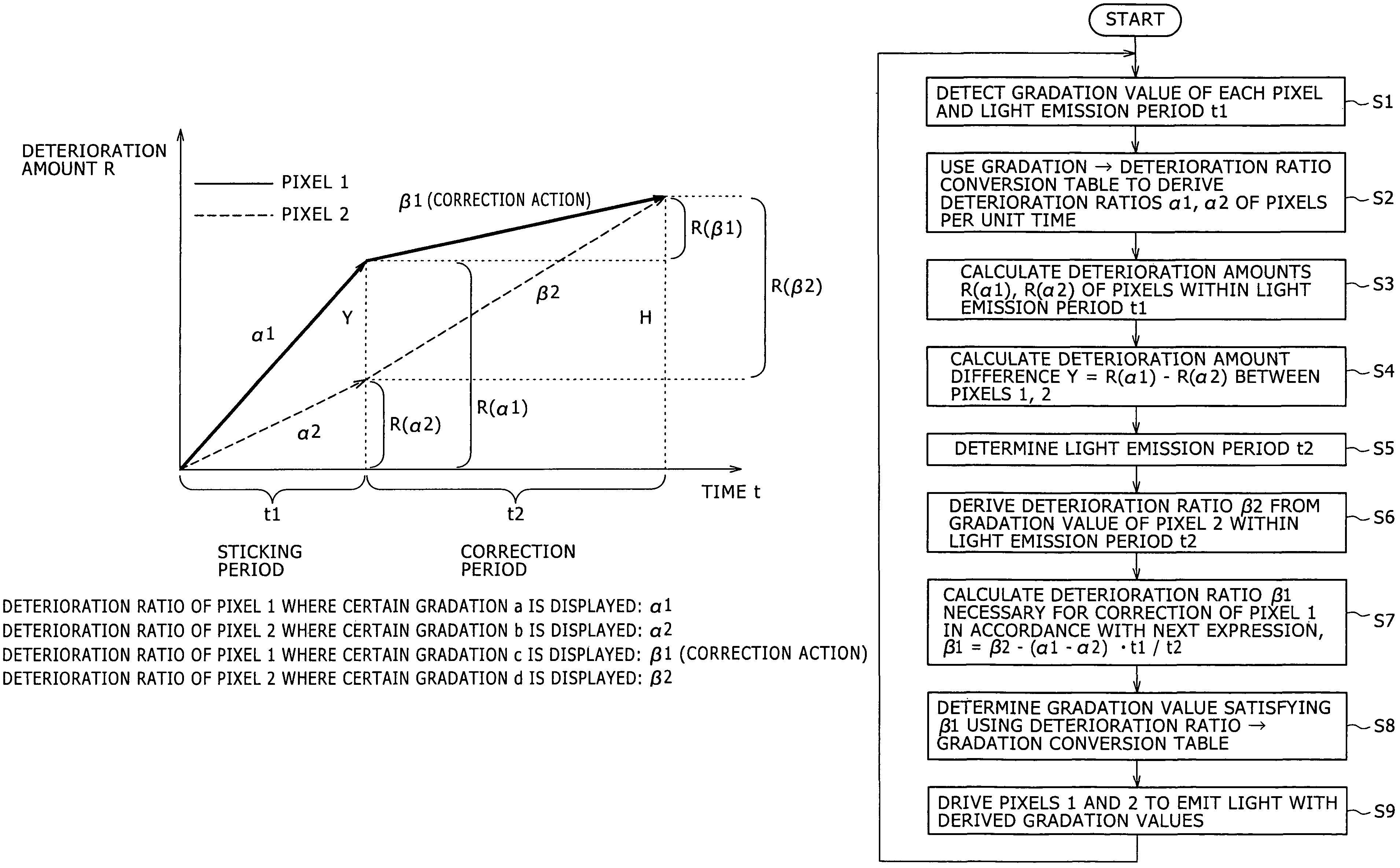
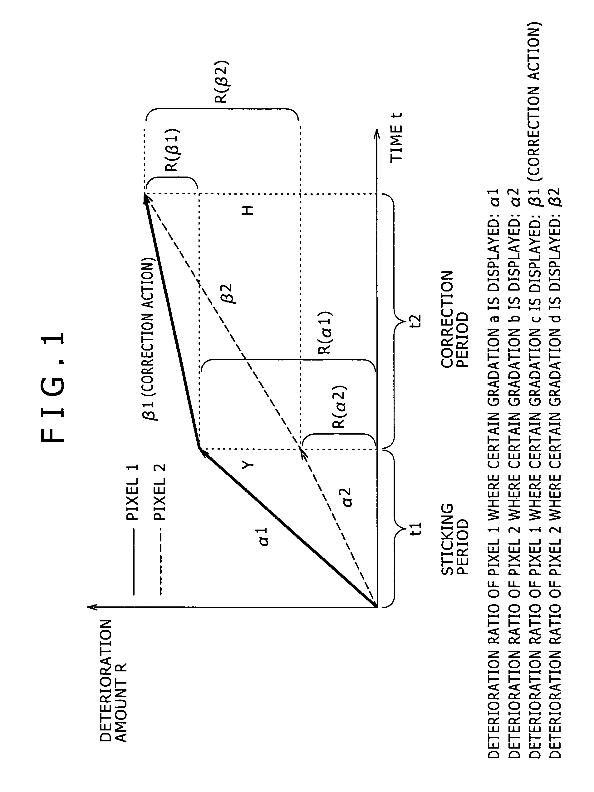
[0102]The deterioration amount difference arithmetic operation section 3 is a processing device which calculates the deterioration amount difference Y appearing between the pixel 1 and the pixel 2 within the light emission period t1. In particular, the deterioration amount difference arithmetic operation section 3 uses the deterioration ratios α1 and α2 corresponding ...

example 2

b. Example 2

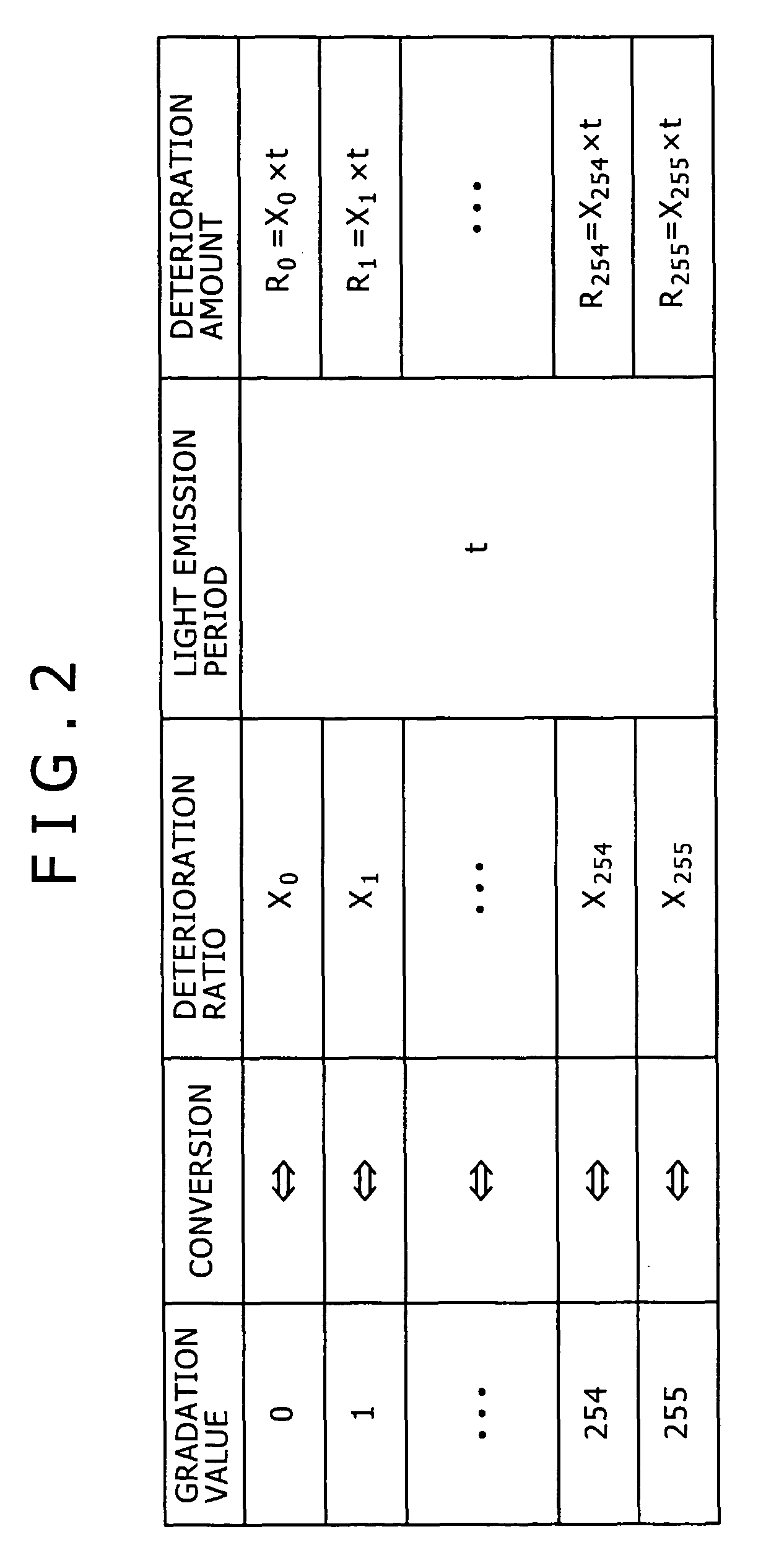
[0107]FIG. 5 shows another example of a form of the sticking phenomenon correction apparatus where it is formed by hardware. The present example corresponds to a case wherein the conversion process from a gradation value to a deterioration ratio and the conversion process from the deterioration ratio to a gradation value are implemented using a conversion table.

[0108]Referring to FIG. 5, the correction apparatus 11 shown includes a deterioration amount conversion section 13, a conversion table 15, a deterioration amount difference calculation section 17, a correction value calculation section 19 and a gradation value correction section 21.

[0109]The deterioration amount conversion section 13, conversion table 15 and deterioration amount difference calculation section 17 correspond to the deterioration amount difference arithmetic operation section 3 described hereinabove. The correction value calculation section 19 corresponds to the correcting deterioration ratio calcula...


PUM


Abstract

A self-luminous apparatus is disclosed wherein a deterioration amount difference between different pixels can be eliminated accurately to correct a sticking phenomenon while the self-luminous apparatus is used. In the self-luminous apparatus, a deterioration amount difference appearing between a correction object pixel and a reference pixel within a first light emission period of time is calculated first using a deterioration ratio derived from gradation values of the pixels. Then, a deterioration ratio for correction for the correction object pixel necessary to eliminate the calculated deterioration amount difference within a second light emission period of time is derived using a deterioration ratio of the reference pixel. Thereafter, the derived deterioration ratio for correction is converted into a corresponding gradation value, and the correction object pixel is driven to emit light with the converted gradation value.

Description

CROSS REFERENCES TO RELATED APPLICATIONS[0001]The present invention contains subject matter related to Japanese Patent Application JP 2005-014830 filed with the Japanese Patent Office on Jan. 21, 2005, the entire contents of which being incorporated herein by reference.BACKGROUND OF THE INVENTION[0002]The present invention relates to a correction method of a sticking phenomenon which appears in a self-luminous apparatus, a sticking phenomenon correction apparatus, a self-luminous apparatus in which a sticking phenomenon correction apparatus is incorporated, and a program for causing a computer incorporated in a self-luminous apparatus to execute a sticking correction process.[0003]A flat panel display unit has spread widely in various products such as computer display units, portable terminal units, television sets and so forth. At present, while a liquid crystal display panel is used frequently, subjects of a limited angular field of view and a low responding speed still remain poi...

Claims


Application Information

Patent Timeline
Patent Type & Authority Patents(United States)
IPC IPC(8): G09G3/30
CPCG09G3/22G09G2320/0285G09G2320/0295G09G2320/046G09G2360/16
Inventor OZAWA, ATSUSHITADA, MITSURU
Owner JOLED INC
Why Eureka
Try Eureka