
Automatic transmission, and apparatus and method of controlling the same

a technology of automatic transmission and transmission shaft, applied in mechanical equipment, digital data processing details, instruments, etc., can solve the problems of inability to absorb inertia torque, inability to carry out automatic transmission, and inability to carry out sufficient inertia torque due to friction, etc., to achieve the effect of carrying out a gear shift quickly and smoothly

Inactive Publication Date: 2010-11-23
JATCO LTD
View PDF13 Cites 12 Cited by
  • Summary
  • Abstract
  • Description
  • Claims
  • Application Information

AI Technical Summary

Benefits of technology

The present invention provides an automatic transmission that can quickly and smoothly absorb inertia torque during gear shifts, even in situations where it is impossible to absorb all of the inertia torque through engine torque reduction. This is achieved by controlling frictional engagement elements so as to cancel out the inertia torque caused by the gear shift. The invention can also compensate for delay in the response of the drive unit and the frictional engagement elements. The technical effect of the invention is to improve the gear shift experience and quality of an automatic transmission.

Problems solved by technology

An automatic transmission may be subject to situations where it is impossible to absorb an inertia torque caused due to change in a rotational state.
Such a sufficient fall of the inertia torque due to friction requires a relatively long time interval.
When the automatic transmission is applied to a motor vehicle, such a gear shift shock may adversely affects the shift feel and ride quality, and cause hard tears and damages in the automatic transmission.

Method used


Image

  • Automatic transmission, and apparatus and method of controlling the same
  • Automatic transmission, and apparatus and method of controlling the same
  • Automatic transmission, and apparatus and method of controlling the same

Examples


first embodiment

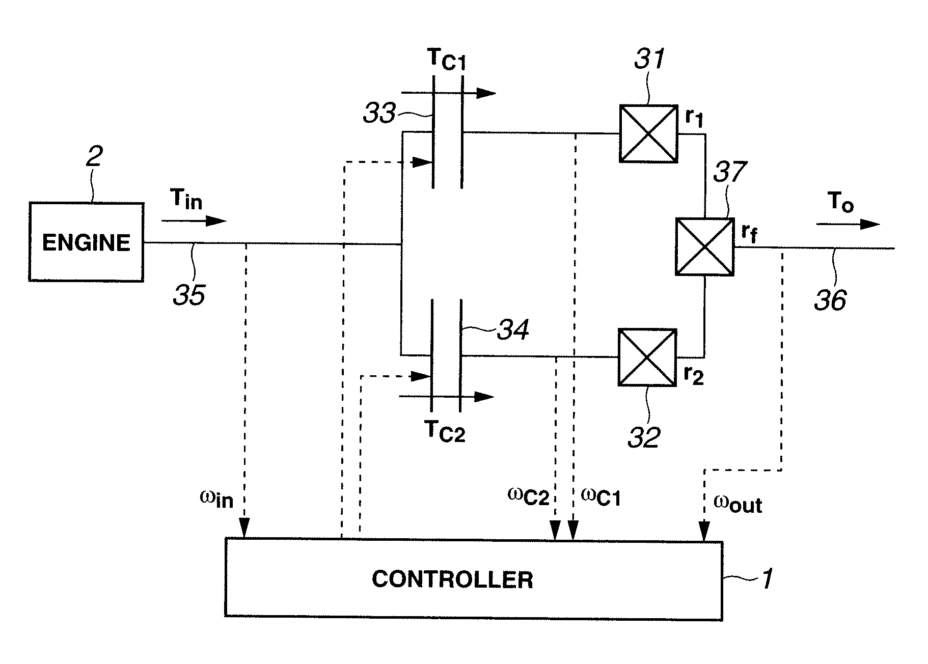
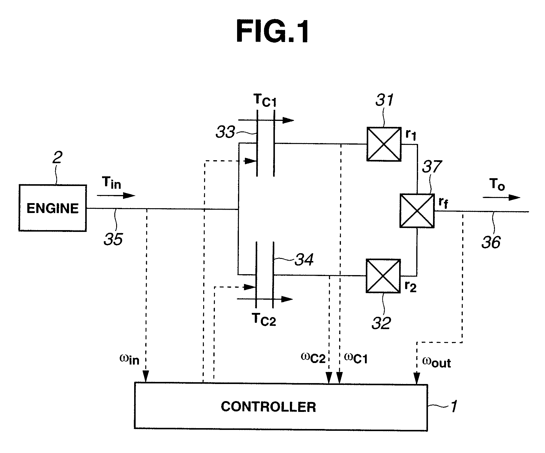
[0086]The following describes a shift control apparatus for controlling clutches so as to cancel the inertia torque in accordance with the present invention with reference to FIGS. 11 to 15C. FIG. 11 shows a section of the shift control apparatus for computing a desired torque capacity correction of each of first and second clutches 33 and 34 for inertia torque cancellation.

[0087]As shown in FIG. 11, first, a calculator 101 computes or calculates a difference (r2−r1) on the basis of the before-shift transmission gear ratio r1 and the after-shift transmission gear ratio r2. A calculator 102 calculates a gain for second clutch 34 by dividing the before-shift transmission gear ratio r1 by the difference (r2−r1). A calculator 103 calculates a gain for first clutch 33 by dividing the after-shift transmission gear ratio r2 by the difference (r2−r1). A calculator 104 calculates a corrected desired clutch-based torque reduction on the basis of a desired clutch-based torque reduction and a c...

second embodiment

[0097]More specifically, the shift control apparatus of the second embodiment sets a target input shaft speed ωin* as indicated by a dashed line in FIGS. 19B and 20B which decreases along a curved line; sets the uncorrected desired torque capacity of each clutch so that input shaft speed ωin follows target input shaft speed ωin*; sets the torque capacity correction of each clutch so as to cancel an inertia torque resulting from change in target input shaft speed ωin*; sets the corrected desired torque capacity of each clutch by adding the uncorrected desired torque capacity and torque capacity correction; and controls the first and second clutches 33 and 34 to attain the corrected desired torque capacity.

[0098]Although input shaft speed ωin is directly controlled in the foregoing description, the difference in first clutch 33 between the input and output speeds (ωC1−ωin) or the difference in second clutch 34 between the input and output speeds (ωin−ωC2) may be controlled. In such ca...


PUM


Abstract

An automatic transmission includes at least an input section, an output section, first and second frictional engagement elements, and a controller. The input section receives an input torque from a drive unit. The first frictional engagement element has an engaged state allowing the output section to rotate at a first transmission gear ratio with respect to the input section. The second frictional engagement element has an engaged state allowing the output section to rotate at a second transmission gear ratio with respect to the input section. The controller controls at least a gear shift from the first transmission gear ratio to the second transmission gear ratio. The controller controls the first and second frictional engagement elements and the drive unit so as to cancel an inertia torque resulting from the gear shift.

Description

BACKGROUND OF THE INVENTION[0001]The present invention relates generally to an automatic transmission with a plurality of frictional engagement elements, and an apparatus and method for controlling such an automatic transmission, and more particularly to canceling an inertia torque caused due to change in a rotational state during a gear shift.[0002]In general, a gear shift of an automatic transmission requires shifting a frictional engagement element such as a clutch from a disengaged state to an engaged state or from an engaged state to disengaged state. It is desired to carry out such a gear shift smoothly and quickly so as to cause no gear shift shock, by suitably operating the frictional engagement element. In the case of an upshift of an automatic transmission, it is desired to absorb an inertia torque caused due to change in a rotational state of the automatic transmission.[0003]Japanese Patent Application Publication No. 10-184410 shows a technique for an upshift of an autom...

Claims


Application Information

Patent Timeline
Patent Type & Authority Patents(United States)
IPC IPC(8): G06F7/00F16H59/14F16H59/42F16H59/68F16H61/08F16H61/68F16H61/684F16H61/686F16H63/50
CPCF16H61/0437Y10T477/677F16H61/68
Inventor KATAKURA, SHUSAKUUCHIDA, MASAAKIKAWAMOTO, YOSHINOBUHONMA, TOMOAKIFUJIWARA, SADAMU
Owner JATCO LTD
Learn More