Heavy equipment concrete core drill bit stabilizer

Active Publication Date: 2019-11-28
THORNTON LEE C
View PDF1 Cites 2 Cited by
  • Summary
  • Abstract
  • Description
  • Claims
  • Application Information

AI Technical Summary

Problems solved by technology

When friction becomes too great, the bit binds and can become stuck in the substrate causing increased we

Method used


Image

  • Heavy equipment concrete core drill bit stabilizer
  • Heavy equipment concrete core drill bit stabilizer
  • Heavy equipment concrete core drill bit stabilizer

Examples


Embodiment Construction

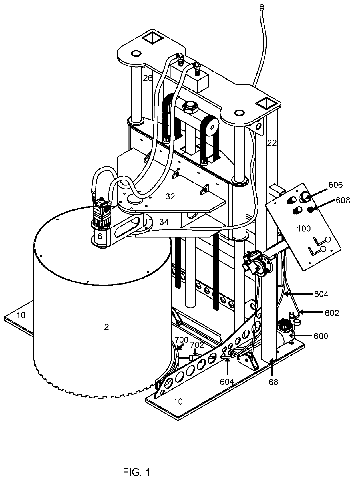
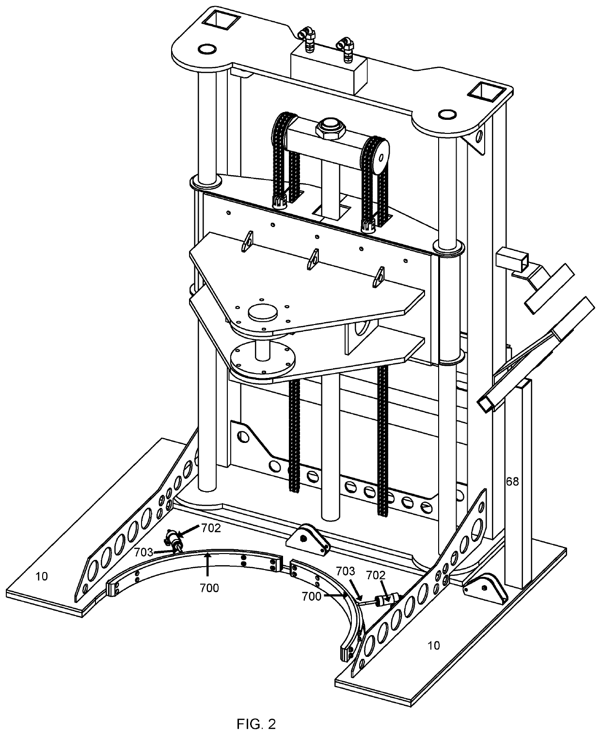
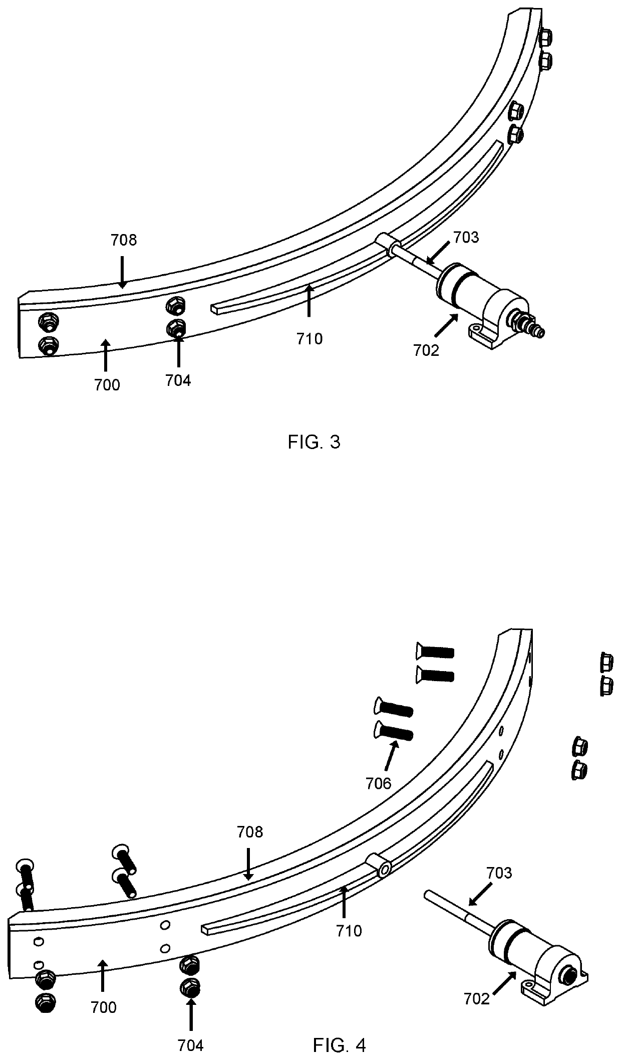
[0021]This application is a continuation-in-part of U.S. Non-Provisional patent application Ser. No. 15 / 990,756. U.S. Non-Provisional patent application Ser. No. 15 / 990,756 is incorporated herein by reference as if fully set forth herein.

[0022]While this invention is susceptible of embodiment in many different forms, there are shown in the drawings and will herein be described in detail, several embodiments with the understanding that the present disclosure should be considered as an exemplification of the principles of the invention and is not intended to limit the invention to the embodiments so illustrated. Further, to the extent that any numerical values or other specifics of materials, etc., are provided herein, they are to be construed as exemplifications of the inventions herein, and the inventions are not to be considered as limited thereto.

[0023]The following description and drawings are illustrative and are not to be construed as limiting. Numerous specific details are des...


PUM

PropertyMeasurementUnit
Pressureaaaaaaaaaa
Diameteraaaaaaaaaa
Frictionaaaaaaaaaa

Abstract

The present invention is an accessory device that hole coring machine, wherein the hole coring machine is utilized to quickly and efficiently core holes in concrete and asphalt. The accessory device comprises a stabilizer assembly that is coupled to a base of the hole coring machine. The stabilizer assembly includes at least one stabilizing frame that is formed to the outside diameter of a drill saw bit of the hole coring machine. The at least one stabilizing frame is coupled to an air compressor that causes the stabilizing frame to move relative to the drill saw bit during operation of the hole coring machine. The at least one stabilizing frame aids in maintaining the shape of the drill saw bit and reduces vibration and binding of the drill saw bit while forming a hole in concrete and/or asphalt.

Description

CROSS-REFERENCE TO RELATED APPLICATIONS[0001]This application is a continuation-in-part of U.S. Non-Provisional patent application Ser. No. 15 / 990,756, and this application claims the benefit of U.S. Non-Provisional patent application Ser. No. 15 / 990,756, filed on May 28, 2018, which names Lee C. Thornton as the inventor.STATEMENT REGARDING FEDERALLY SPONSORED RESEARCH OR DEVELOPMENT[0002]Not Applicable.THE NAMES OF THE PARTIES TO A JOINT RESEARCH AGREEMENT[0003]Not applicable.INCORPORATION-BY-REFERENCE OF MATERIAL SUBMITTED ON A COMPACT DISC OR AS A TEXT FILE VIA THE OFFICE ELECTRONIC FILING SYSTEM[0004]Not applicable.STATEMENT REGARDING PRIOR DISCLOSURES BY THE INVENTOR OR JOINT INVENTOR[0005]The inventor did not disclose the invention herein prior to the 12 month period preceding the filing of this non-provisional continuation-in-part application.BACKGROUND OF THE INVENTION(1) Field of the Invention[0006]Commercial and industrial sites often require a concrete or asphalt slab to ...

Claims


Application Information

Patent Timeline
IPC IPC(8): E21B10/02E21B10/62
CPCB28D1/041E21B7/027E21B10/02E21B19/24B28D1/04E21B10/62
Inventor THORNTON, LEE C.
Owner THORNTON LEE C
Why Eureka
Try Eureka