DTV transmitting system and receiving system and method of processing broadcast signal

a transmitting system and broadcast signal technology, applied in the field of digital telecommunications systems, can solve the problems of data that is to be transmitted should have a low error ratio, the quality of the received digital signals may be deteriorated, and the intensity of signals may decrease, so as to enhance the receiving performance of the receiving system

Inactive Publication Date: 2010-11-23
LG ELECTRONICS INC
View PDF11 Cites 57 Cited by
  • Summary
  • Abstract
  • Description
  • Claims
  • Application Information

AI Technical Summary

Benefits of technology

[0010]Another object of the present invention is to provide a DTV transmitting system and a DTV receiving system and a method of processing broadcast signal that can perform additional encoding and create hierarchical areas in accordance with the importance of the enhanced data, thereby enhancing the receiving performance of the receiving system.
[0011]A further object of the present invention is to provide a DTV transmitting system and a DTV receiving system and a method of processing broadcast signal that can divide the known data, which are known by the transmitting and receiving systems, and the enhanced data into hierarchical areas and that can multiplexed the divided data with the main data, thereby enhancing the receiving performance of the receiving system.

Problems solved by technology

However, when used indoors, the intensity of the signals may decrease due to a blockage caused by the walls or disturbance caused by approaching or proximate mobile objects.
Accordingly, the quality of the received digital signals may be deteriorated due to a ghost effect and noise caused by reflected waves.
However, unlike the general video / audio data, when transmitting the supplemental data, the data that is to be transmitted should have a low error ratio.
Conversely, in case of the supplemental data (e.g., program execution file, stock information, etc.), an error even in a single bit may cause a serious problem.
Furthermore, in a poor channel environment, the receiving performance of the conventional receiving system may be deteriorated.

Method used


Image

  • DTV transmitting system and receiving system and method of processing broadcast signal
  • DTV transmitting system and receiving system and method of processing broadcast signal
  • DTV transmitting system and receiving system and method of processing broadcast signal

Examples


Embodiment Construction

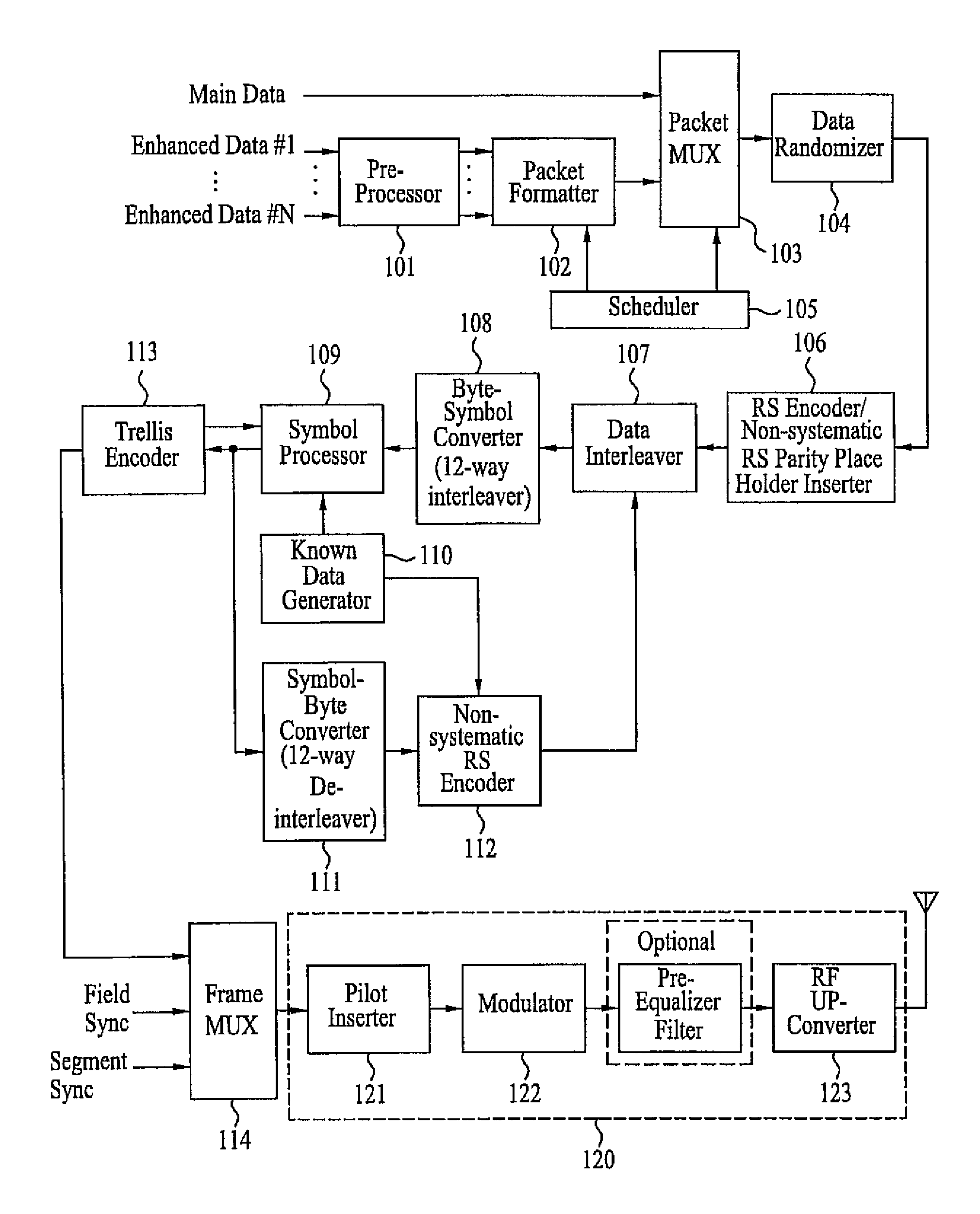
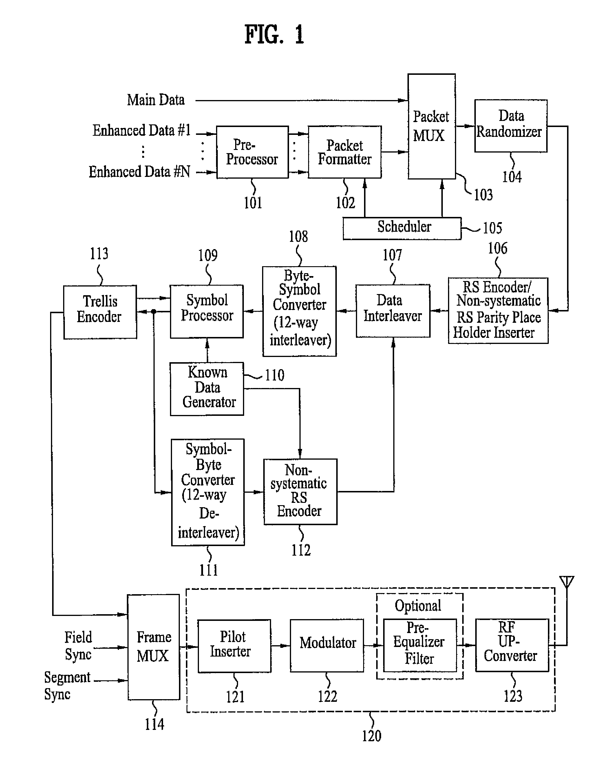
[0026]Reference will now be made in detail to the preferred embodiments of the present invention, examples of which are illustrated in the accompanying drawings. Wherever possible, the same reference numbers will be used throughout the drawings to refer to the same or like parts. In addition, although the terms used in the present invention are selected from generally known and used terms, some of the terms mentioned in the description of the present invention have been selected by the applicant at his or her discretion, the detailed meanings of which are described in relevant parts of the description herein. Furthermore, it is required that the present invention is understood, not simply by the actual terms used but by the meaning of each term lying within.

[0027]In the present invention, the enhanced data may either consist of data including information such as program execution files, stock information, and so on, or consist of video / audio data. Additionally, the known data refer ...


PUM


Abstract

A DTV transmitting system includes a first pre-processor for coding first enhanced data having a high priority for forward error correction (FEC) at a first coding rate and expanding the first enhanced data at a first expansion rate, and a second pre-processor for coding second enhanced data having a low priority for FEC at a second coding rate and expanding the second enhanced data at a second expansion rate. The receiving system further includes a data formatter for generating enhanced data packets, a multiplexer for multiplexing the enhanced data packets with main data packets, an RS encoder for RS-coding the multiplexed data packets, and a data interleaver for interleaving the RS-coded data packets and outputting a group of interleaved data packets having a head, a body, and a tail.

Description

[0001]This application claims the benefit of the Korean Patent Application No. 10-2006-0019649, filed on Feb. 28, 2006, which is hereby incorporated by reference as if fully set forth herein. Also, this application claims the benefit of the Korean Patent Application No. 10-2006-0089736, filed on Sep. 15, 2006, which is hereby incorporated by reference as if fully set forth herein. This application also claims the benefit of U.S. Provisional Application No. 60 / 883,305, filed on Jan. 3, 2007, which is hereby incorporated by reference.BACKGROUND OF THE INVENTION[0002]1. Field of the Invention[0003]The present invention relates to a digital telecommunications system, and more particularly, to a DTV transmitting system and receiving system and method of processing broadcast signal that can receive and transmit digital broadcast signal.[0004]2. Discussion of the Related Art[0005]Presently, the technology for processing digital signals is being developed at a vast rate, and, as a larger nu...

Claims


Application Information

Patent Timeline
Patent Type & Authority Patents(United States)
IPC IPC(8): H03M13/00H04N5/00
CPCH04L1/0047H04L1/0065H04L1/007H04L1/0071H04N21/23412H04N21/2383H04N21/4382H04N19/37H03M13/2936H04L25/03019H04L27/0014
Inventor LEE, HYOUNG GONCHOI, IN HWANKWAK, KOON YEON
Owner LG ELECTRONICS INC
Why Eureka
Try Eureka