Heat exchange apparatus

a technology of heat exchange apparatus and heat exchanger tube, which is applied in the direction of submerged flame steam boiler, steam generation using hot heat carriers, steam generation using pressure, etc., can solve the problems of sediment from heavy oil, blockage of supply lines, and none of them have been found to be fully satisfactory, and achieve the effect of increasing the heat exchange capacity of the heat exchanger tub

Active Publication Date: 2010-11-30
TECVALCO LTD
View PDF22 Cites 14 Cited by
  • Summary
  • Abstract
  • Description
  • Claims
  • Application Information

AI Technical Summary

Benefits of technology

[0051]The heat exchanger tubes are preferably comprised of opposed ends and at least one of the opposed ends is preferably in fluid communication with the heat exchange vessel so that the heat exchange fluid can enter the heat exchanger tube, preferably within the sump section of the heat exchange vessel. Each of the heat exchanger tubes is preferably further comprised of one or more fins for increasing the heat exchanging capacity of the heat exchanger tube.

Problems solved by technology

Specifically, small amounts of water typically entrained within the natural gas may freeze, causing a blockage of the supply line.
This problem is enhanced in colder climates where the natural gas entering the pressure reduction station is already at a reduced or colder temperature.
In addition, sediment from the heavy oil tends to settle or collect at the bottom of the storage tank.
However, none have been found to be fully satisfactory.

Method used


Image

  • Heat exchange apparatus
  • Heat exchange apparatus
  • Heat exchange apparatus

Examples


Embodiment Construction

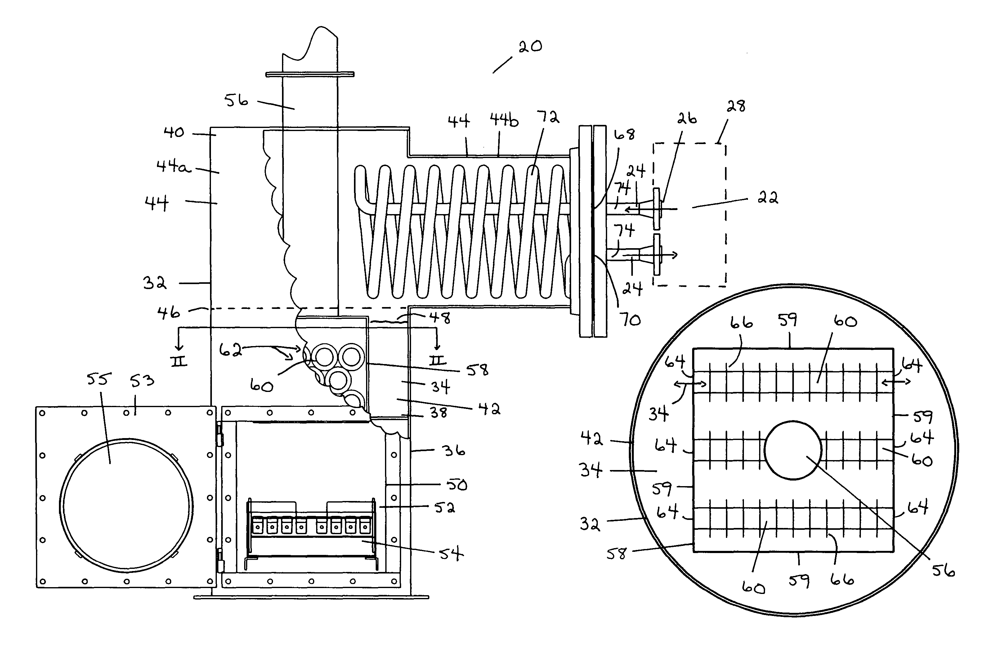
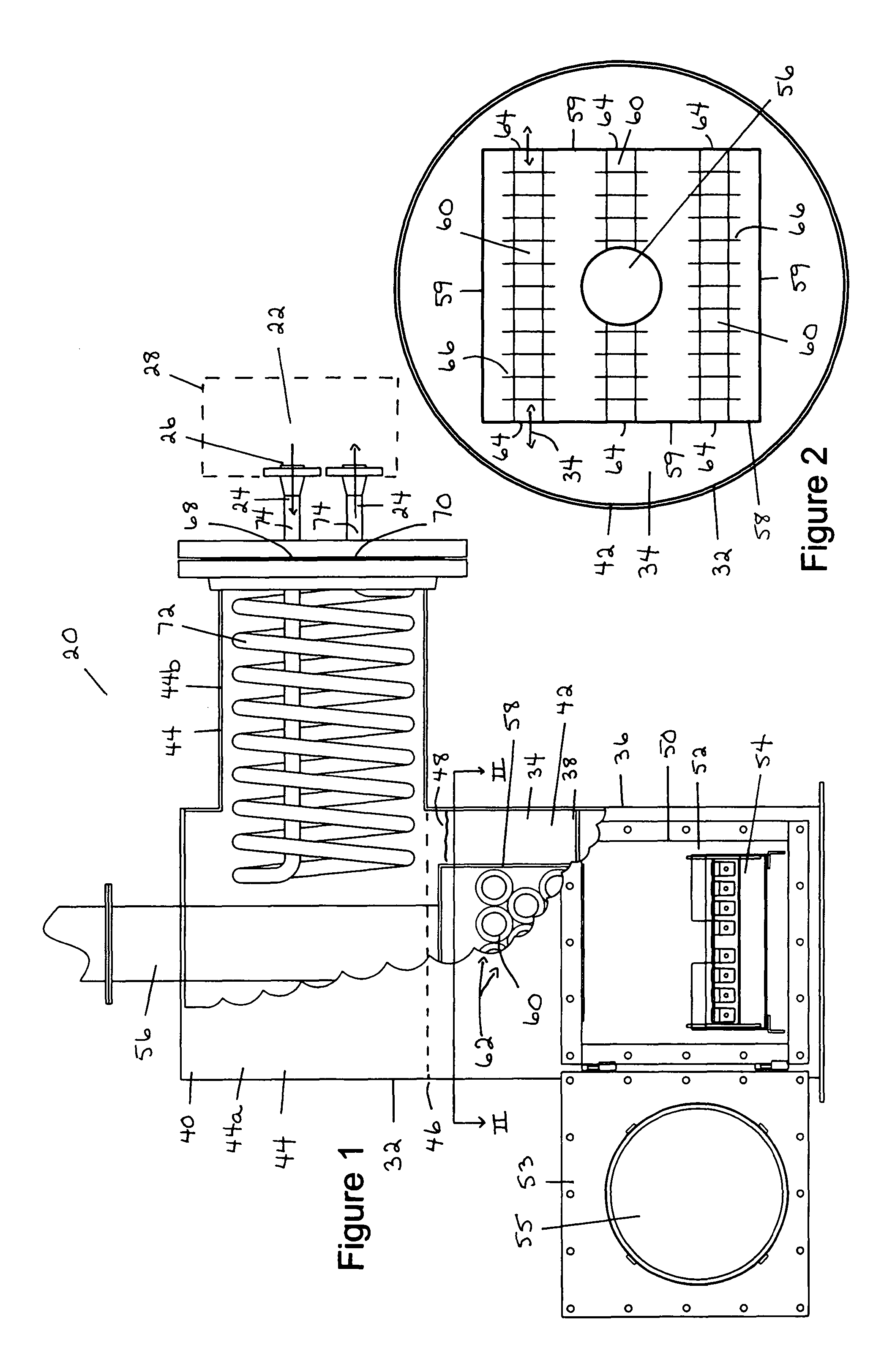
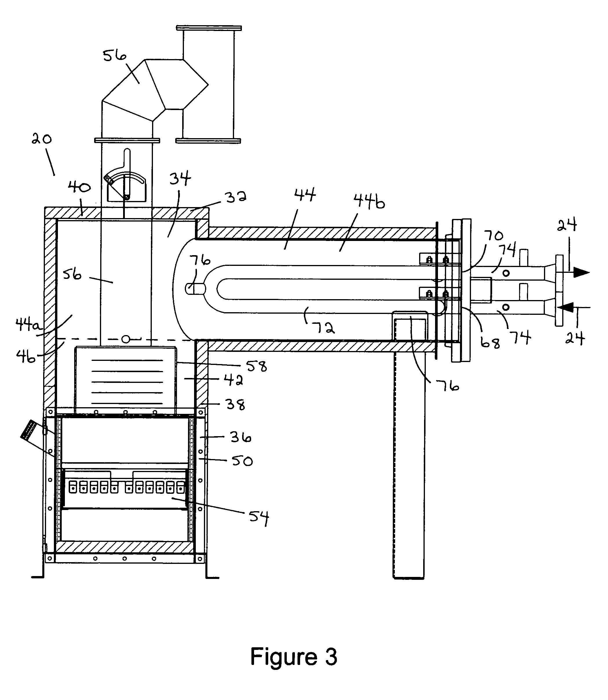
[0074]Referring to FIGS. 1-13, a heat exchange apparatus (20) is provided for use in transferring heat to a heat sink (22). The heat sink (22) may be comprised of any structure, device, apparatus or material which is required or desired to be heated. Preferably, the heat sink (22) includes, contains or is comprised of a target fluid (24) which is desired or required to be heated. Thus, the heat exchange apparatus (20) is particularly used for heating, or transferring heat to, the target fluid (24). The target fluid (24) may be any type or composition of fluid desired to be heated, including any liquid or gas suitable for heating with the heat exchange apparatus (20).

[0075]As indicated, the heat exchange apparatus (20) may be used with any type or form of heat sink (22) and may be used for either an “outside-in” heating application or an “inside-out” heating application. In an “outside-in” heating application, the target fluid (24) comprising the heat sink (22) is passed within, into...


PUM


Abstract

A heat exchange apparatus for use in transferring heat to a heat sink. Preferably, the heat sink is comprised of a natural gas supply line at a pressure reduction station. Alternately, the heat sink is comprised of a storage tank. The apparatus is comprised of a heat exchange vessel, adapted to contain an amount of a heat exchange fluid, and a heat source. The heat exchange vessel includes a sump section at a lower end thereof, and a heat transfer section for transferring heat to the heat sink. The heat exchange vessel further includes a single communication junction between the sump section and the heat transfer section which provides fluid communication therebetween. The heat source is associated with the sump section and adapted to add heat to the heat exchange fluid in order to cause the heat exchange fluid to evaporate in the heat exchange vessel.

Description

FIELD OF INVENTION[0001]The present invention relates to a heat exchange apparatus for use in transferring heat to a heat sink. Preferably, the heat sink is comprised of natural gas from a natural gas supply line at a pressure reduction station or a produced fluid contained within a storage tank.BACKGROUND OF INVENTION[0002]In the distribution of natural gas, the natural gas is conducted from its source in a natural gas supply line at a relatively high pressure. Prior to providing the natural gas to an end user or natural gas customer, a pressure reduction must occur in the natural gas supply line to reduce the pressure of the natural gas to an intermediate pressure or desired level compatible with and suitable for distribution to the end user. To accomplish this function, pressure reduction stations, also known as gate stations or regulating stations, are provided. The pressure reduction station includes pressure reducing valves which reduce the pressure of the natural gas within t...

Claims


Application Information

Patent Timeline
Patent Type & Authority Patents(United States)
IPC IPC(8): F22B1/02
CPCF28D1/0213F17D1/04F28D15/0266F28D15/02
Inventor KING, J. WAYNEROSS, BLAINE D.
Owner TECVALCO LTD
Why Eureka
Try Eureka