Transverse connector

a cross-connector and connector technology, applied in the field of cross-connector or connecting assembly, can solve the problems of cross-connectors with multiple points of articulation and multiple locking mechanisms that are difficult to implement in miss applications, and the number of obstacles is commonly encountered, so as to avoid the potential for cross-threading, avoid unwanted stress and physical damage to the rod, and minimize the effect of the connecting device and the actuator itsel

Active Publication Date: 2010-11-30
XTANT MEDICAL HLDG INC
View PDF101 Cites 72 Cited by
  • Summary
  • Abstract
  • Description
  • Claims
  • Application Information

AI Technical Summary

Benefits of technology

[0015]In another form, operating the actuators secures the spinal rods to the transverse connecting assembly and simultaneously locks the points of articulation within the connector assembly, preventing relative movement of the rod receiving devices and spinal rods.
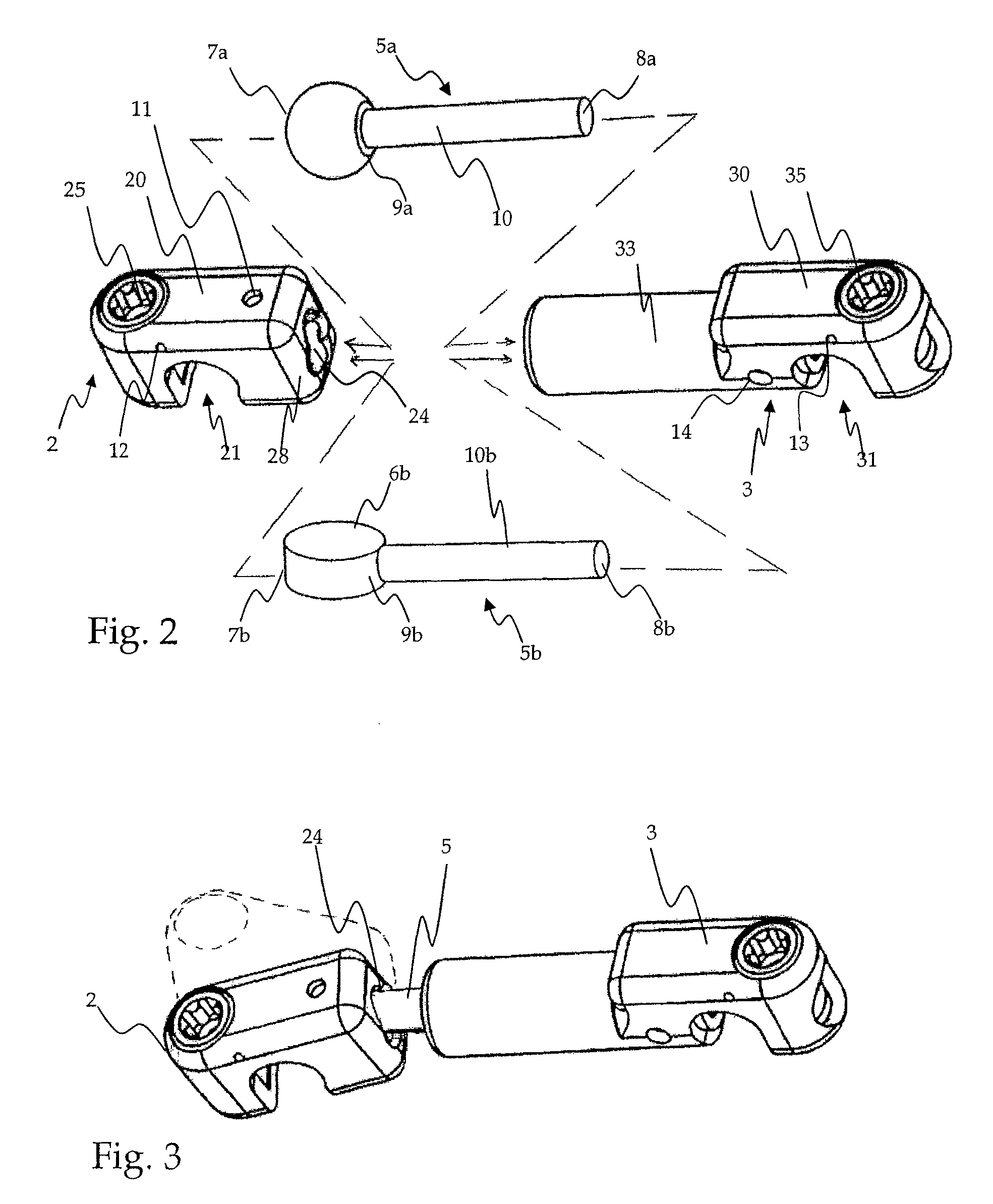
[0021]One or both ends of the cross rod may be configured for articulation. The actuators serve to lock these points of articulation, preventing movement of the cross rod relative to the rod receiving device housing the actuator. In one aspect, a first rod receiving device has a first rotatable actuator member and an opening for pivotably receiving the first end of a cross rod, while the second rod receiving device has a second rotatable actuator member and an opening slidably and rotatably receiving a second end of the cross rod so that the second end of the cross rod may be shifted to an adjusted depth and rotated about its axis within the second rod receiving device. In one form, manipulating the first actuator member simultaneously secures a first spinal rod within the first rod receiving device and locks the first end of the cross rod against pivotal movement, while manipulation of the second actuator member simultaneously secures the second spinal rod within the second rod receiving device and locks the second end of the cross rod against axial and rotational movement. In this manner, operating only two actuator members is effective to fully lock the first spinal rod, second spinal rod, and the cross rod, thereby preventing linear, rotational, and pivotal movement of the spinal rods and cross rod with respect to the first and second rod receiving devices.
[0025]Advantageously, the actuator members may be comprised of a material that is harder than the material that makes up the spinal rod. For instance, if the spinal rods are made of titanium, actuators formed from cobalt-chromium may be provided to lock the rods in place. It has been found that actuators of harder materials provide greater locking force than those made of softer materials, and that actuators made of material harder than the material of the spinal rods that they engage provides an especially strong locking force.
[0027]Advantageously, a structure forming a hard stop may also be provided so that the actuator has a predetermined locked position. An actuator with a predetermined locked position provides a surgeon with certainty, since it is known that the device is locked when the actuator is rotated by a predetermined amount. Without a predetermined locked position, for instance when set screws are used as securing devices and tightened until a locking force is applied and the screw is fully engaged with its target, the surgeon must determine whether or not the set screw “feels” secured. This may result in a failure to lock the device or accidental over-torquing. An actuator with a set locked position also avoids the potential for cross-threading, another problem also associated with set screws. Therefore, unwanted stress and physical damage to the rod, connecting device, and the actuator itself are minimized by providing a preset locked position. In addition, the predetermined locked position is especially useful in MISS applications, where the surgeon often cannot see the implant.
[0028]In minimally invasive surgical systems for connecting spinal rods, a connecting assembly comprising two rod receiving devices connected by a cross rod may be implanted through a small incision, with or without an elongate guide tube or docking sleeve. The connecting assembly preferably has at least one seat for receiving a spinal rod, and at least one actuator member. If a guide tube is used, any tools used to manipulate the actuator or other portions of the assembly should be adapted to fit through the tube in order to operate the actuator member. Since the view through the guide tube is ordinarily obstructed by the tool, a stop may be provided to keep the tool from turning or otherwise operating the actuator member by more than a first predetermined amount so that the assembly need not be inspected to determine if the actuator has been properly manipulated.
[0029]In one form, the connecting assembly, or one of the rod receiving devices of such an assembly, is inserted into the body in a MISS surgical procedure. A relatively small incision is formed at a surgical site adjacent a first spinal rod. A guideway is confined through the small incision in order to form a guide to the site of implantation, through which the assembly and tools used to manipulate the connecting assembly may pass. A spinal rod at the site of implantation is engaged with a seat of the connecting assembly, and an actuator of the assembly is manipulated using a tool passing through the guideway. Preferably, the actuator is moved to a first predetermined position to secure the rod, and restricted from moving beyond the first predetermined position. The actuator may also have further predetermined positions. In one form, the actuator is rotated to a first predetermined rotary position, where the assembly is loosely secured to the rod so that the cross rod or other portions of the assembly may be adjusted, and then rotated to a second predetermined rotary position effective for fixing the connecting assembly against movement along the spinal rod.

Problems solved by technology

While incisions are required during such surgical procedures in order to gain access to the site where the implant is secured, such incisions can cause damage, injury, and trauma to the patient's body.
When utilizing crosslinking or connecting devices to secure pedicle screws, a number of obstacles are commonly encountered.
However, providing multiple points of articulation presents further problems.
Additionally, cross connectors with multiple points of articulation and multiple locking mechanisms are often difficult to implement in MISS applications, since the surgeon must gain access to each of the locking mechanisms, which in many transverse connector systems are located on the cross rod portion traversing the gap between the two spinal rods.
Often, the patient's soft tissue must be cleared for this purpose, a result which may exacerbate pain, discomfort, and healing time.
When a set screw drives against a spinal rod or other fixture, damage and distortion may occur at the interface.
This can lead to uneven securement by the set screw, localized weakening of the fixture, loosening of the screw, or debris ground from either the screw or the fixture.
Additionally, the screws require a threaded path long enough to provide a secure hold for the screw, which adds to the material cost, to the size of the fixture, and to the invasiveness of the procedure.
Moreover, the use of a set screw in the central fastening area presents a danger to the patient.

Method used


Image

  • Transverse connector
  • Transverse connector
  • Transverse connector

Examples


Embodiment Construction

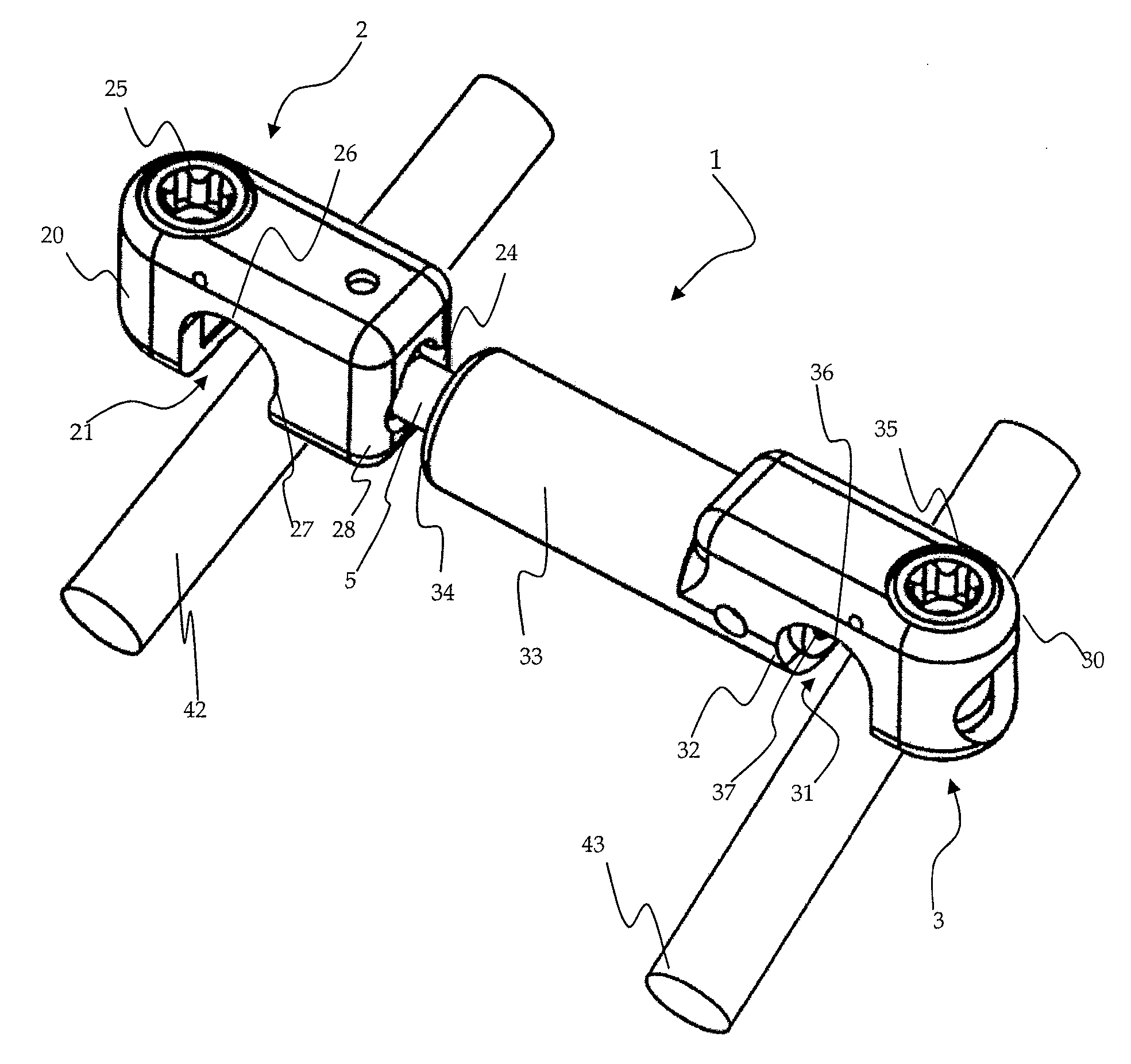
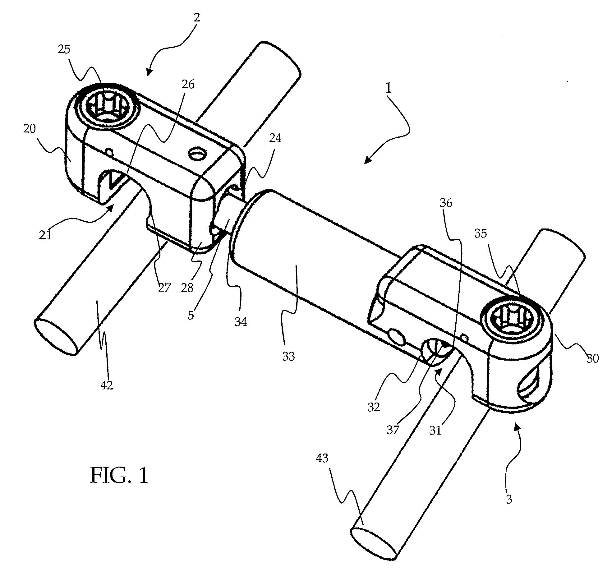
[0049]One embodiment of a transverse connecting assembly 1 for connecting two spinal rods 42 and 43 is shown in perspective by FIG. 1. The connecting assembly 1 comprises a first rod receiving device 2, a second rod receiving device 3, and a cross rod 5.

[0050]The first rod receiving device includes a rod receiving body 20 with a U-shaped recess 21 for receiving a spinal rod and a lateral opening 24 for receiving the cross rod 5. The recess 21 has an arcuate upper surface 26 and forms a seat configured to engage the surface of the spinal rod 42. A rotatable actuator 25 is disposed in the rod receiving body 20 adjacent to the recess 21. A side opening 24 in the side wall 28 of the body is sized so that the cross rod 5 may pivot. The opening 24 may be configured to permit pivoting of the cross rod 5 in one or more directions. Preferably, the cross rod 5 may pivot 360 degrees in the opening 24. In order to secure the first rod receiving device 2 to the spinal rod 42, the arcuate seat su...


PUM


Abstract

A crosslink or connecting assembly is provided to secure multiple spinal rods in relation to each other. The connecting assembly is disposed transversely between two spinal rods and has moveable components for rotating, pivoting, and extending portions of the connecting device in order to accommodate the positioning of the spinal rods.

Description

FIELD OF THE INVENTION[0001]The invention relates to a crosslink or connecting assembly and method to secure multiple spinal rods in relation to each other and, in particular, to a connecting assembly disposed transversely between two spinal rods that has moveable components for rotating, pivoting, and extending portions of the connecting device, as well as actuating members for locking the moveable components in place.BACKGROUND OF THE INVENTION[0002]In surgical procedures involving the spine, it is common to secure a pair of spinal rods to a series of vertebrae so that the rods are aligned essentially parallel to the spinal column. The spinal rods may serve to immobilize vertebrae, preventing unwanted flexion, extension, and rotation of vertebrae with respect to each other. It is often further desirable, or even necessary, to provide a connecting device to extend transversely between spinal rods, thereby securing the spinal rods relative to each other.[0003]Spinal rods are typical...

Claims


Application Information

Patent Timeline
Patent Type & Authority Patents(United States)
IPC IPC(8): A61B17/70
CPCA61B17/7052
Inventor HAWKES, DAVID T.
Owner XTANT MEDICAL HLDG INC
Why Eureka
Try Eureka