Modified distributed amplifier to improve low frequency efficiency and noise figure

a distributed amplifier and low frequency efficiency technology, applied in amplifiers, amplifiers with coupling networks, amplifiers with semiconductor devices/discharge tubes, etc., can solve the problems of low efficiency of traditional distributed amplifier systems, destructive interference of reverse waves, and little power is absorbed into output transmission circuit terminations, so as to reduce the overall noise figure of amplifier systems and reduce low frequency loss.

Active Publication Date: 2010-11-30
HITTITE MICROWAVE LLC
View PDF12 Cites 8 Cited by
  • Summary
  • Abstract
  • Description
  • Claims
  • Application Information

AI Technical Summary

Benefits of technology

[0005]It is a further object of this invention to provide such an improved distributed amplifier system with improved low frequency efficiency.
[0007]It is a further object of this invention to provide such an improved distributed amplifier system which maintains predetermined impedance of the system while improving low frequency efficiency and noise figure.
[0008]It is a further object of this invention to provide such an improved distributed amplifier system which provides better performance over an extended bandwidth on a single chip.
[0009]The invention results from the realization that an improved distributed amplifier system with improved low frequency efficiency and noise figure can be achieved by feedback-connecting the output termination to the input transmission circuit thereby allowing the output termination resistance to be increased causing the input signal to prefer propagation along the output transmission circuit relative to output termination resulting in better low frequency efficiency, while the feedback connection to the input transmission circuit results in the output impedance remaining at a predetermined level and further allowing an increase in the input termination resistance to reduce noise figure while maintaining the input impedance at a predetermined level.
[0011]This invention features a distributed amplifier system having a predetermined input and output impedance including: an input transmission circuit; an output transmission circuit; and at least two amplifiers connected between the input and output transmission circuits. There is an input termination on the input transmission circuit and a feedback output termination on the output transmission circuit connected back to the input transmission circuit for reducing low frequency loss while maintaining the predetermined output impedance and input impedance.
[0012]In a preferred embodiment the plurality of amplifiers may include two amplifiers. The amplifiers may include cascode amplifiers. The input termination may include an input resistance and an input capacitance connected in series to ground. The output termination may include an output resistance and an output capacitance connected in series. The output resistance may be substantially larger than the predetermined output impedance. The input resistance may be at least twice the predetermined output impedance. The output resistance may be in the range of two to twenty times the predetermined output impedance. The input resistance may be substantially larger than the predetermined input impedance for reducing the overall noise figure of the amplifier system. The feedback output termination may be fed back to the input of the input transmission circuit. There may be more than one feedback output termination connection between the output transmission circuit and the input transmission circuit.

Problems solved by technology

The signal traveling to the output will constructively interfere so that the signal grows along the drain line (output transmission circuit).
Any reverse waves will destructively interfere since these signals will not be in phase.
The traditional distributed amplifier system suffers from poor efficiency as many of the amplifiers in the chain are not optimally matched for power.
In the GHz range, the signal traveling to the output will constructively interfere and grow while any reverse waves will destructively interfere and decrease so that very little power is absorbed into the output transmission circuit termination.

Method used


Image

  • Modified distributed amplifier to improve low frequency efficiency and noise figure
  • Modified distributed amplifier to improve low frequency efficiency and noise figure
  • Modified distributed amplifier to improve low frequency efficiency and noise figure

Examples


Embodiment Construction

[0022]Aside from the preferred embodiment or embodiments disclosed below, this invention is capable of other embodiments and of being practiced or being carried out in various ways. Thus, it is to be understood that the invention is not limited in its application to the details of construction and the arrangements of components set forth in the following description or illustrated in the drawings. If only one embodiment is described herein, the claims hereof are not to be limited to that embodiment. Moreover, the claims hereof are not to be read restrictively unless there is clear and convincing evidence manifesting a certain exclusion, restriction, or disclaimer.

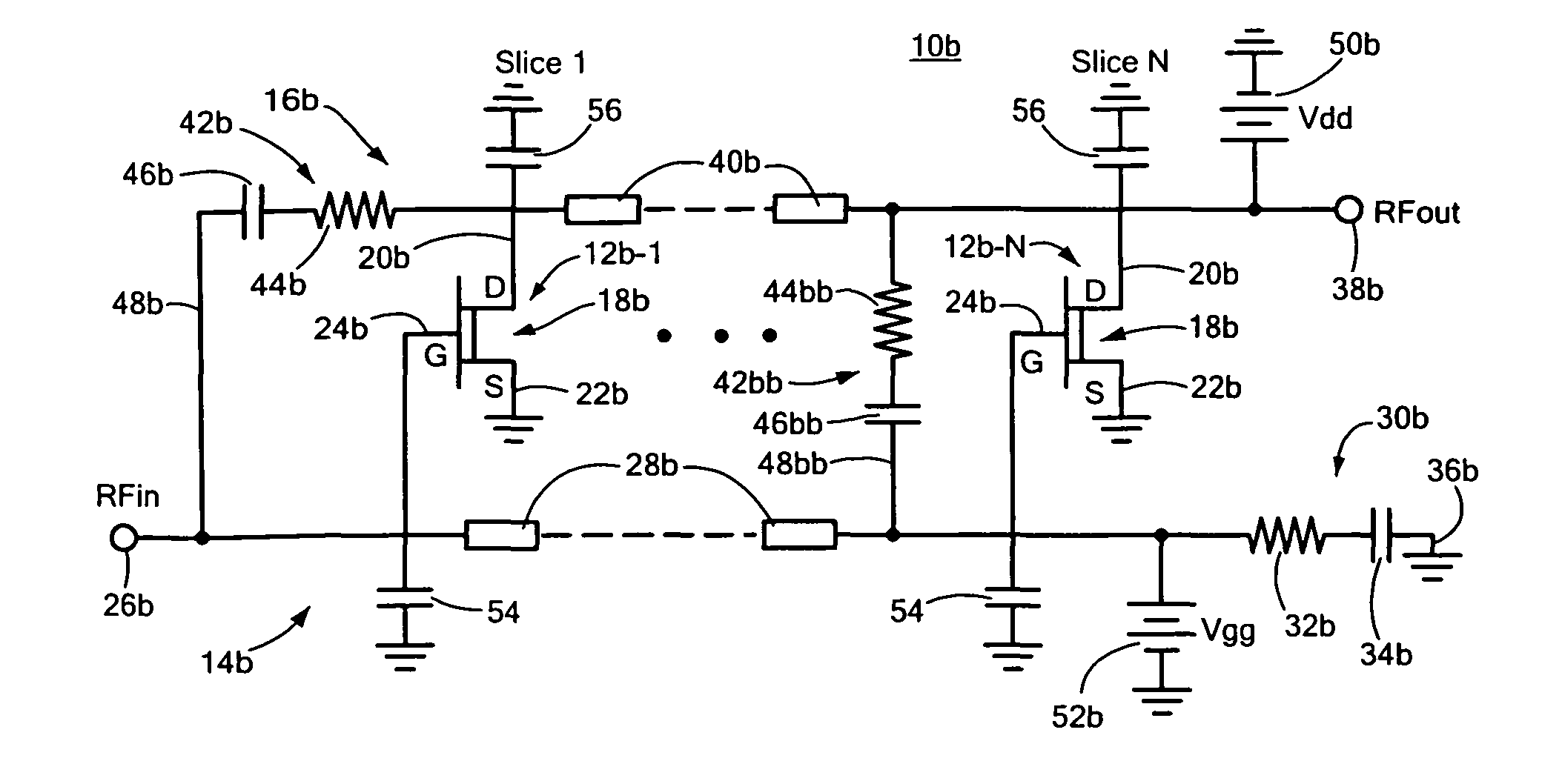
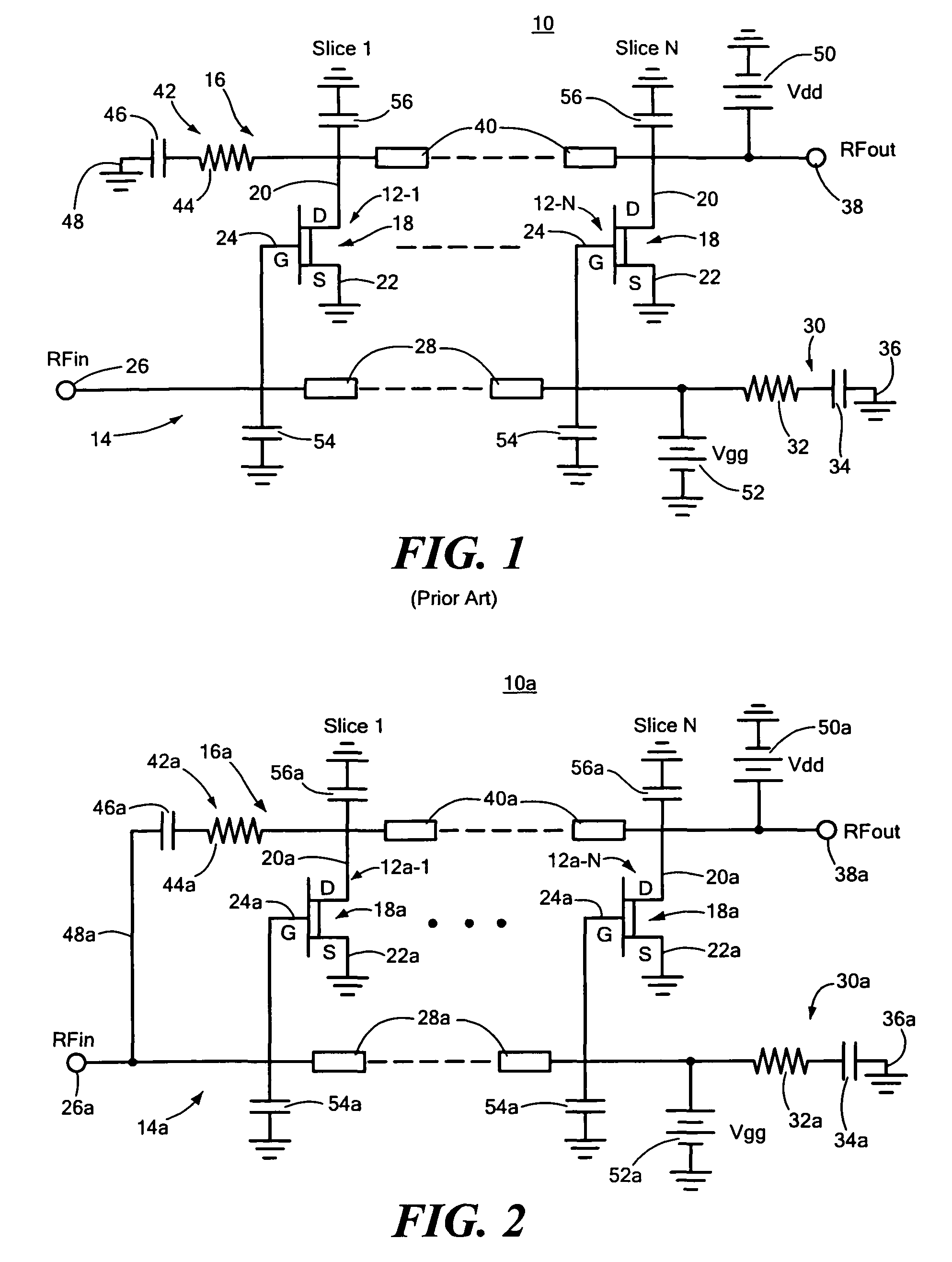
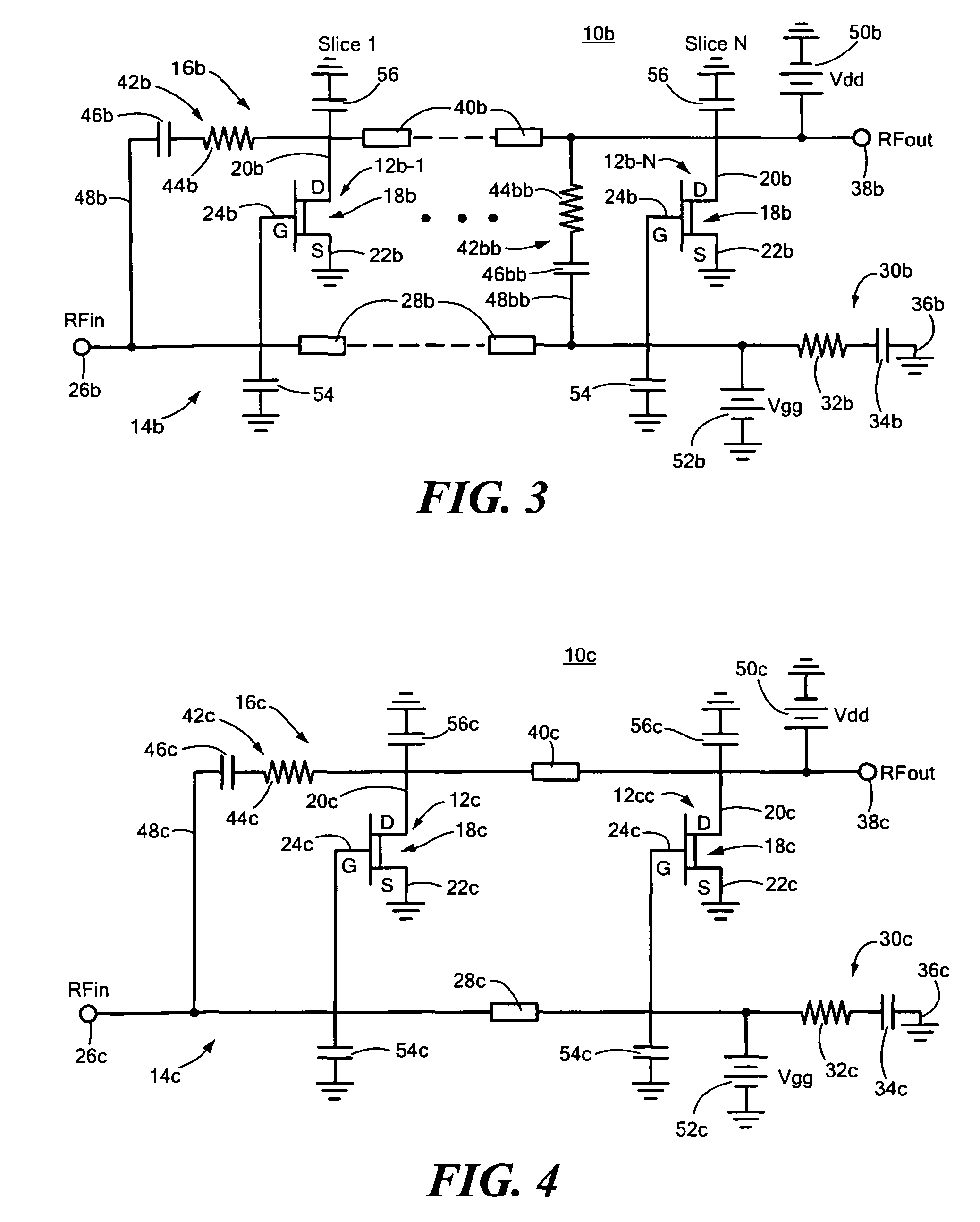
[0023]There is shown in FIG. 1 a prior art distributed amplifier system 10 including a plurality of at least two slices or amplifiers 12-1 through 12-N each of which is interconnected between an input transmission circuit 14 and an output transmission circuit 16. Each slice or amplifier 12-1 through 12-N includes a field ef...


PUM


Abstract

A distributed amplifier system has a predetermined output impedance and input impedance and includes an input transmission circuit; an output transmission circuit; at least two amplifiers connected between the input and output transmission circuits; an input termination on the input transmission circuit; and a feedback output termination on the output transmission circuit connected back to the input transmission circuit for reducing low frequency loss while maintaining the predetermined output impedance and input impedance.

Description

RELATED APPLICATIONS[0001]This invention was made with U.S. Government support under Contract No. W15P7T-06-C-P218 by the U.S. Army. The Government has certain rights in the subject invention.FIELD OF THE INVENTION[0002]This invention relates to an improved distributed amplifier system with improved low frequency efficiency and noise figure.BACKGROUND OF THE INVENTION[0003]A traditional distributed amplifier system is a proven way to build a wideband amplifier. Typical bandwidths of distributed amplifiers on a GaAs substrate could be on the order of 10 kHz-10 GHz. A cascode distributed amplifier is widely recognized as a way to improve gain and bandwidth over a non-cascode distributed amplifier. The benefit of a distributed amplifier system is accomplished by incorporating the parasitic effects of the transistor into the matching networks between amplifiers (slices). The input and output capacitances of the system can be combined with the gate line (input transmission circuit) and d...

Claims


Application Information

Patent Timeline
Patent Type & Authority Patents(United States)
IPC IPC(8): H03F3/60
CPCH03F1/223H03F1/342H03F3/607H03F2200/144
Inventor BENSON, KEITH
Owner HITTITE MICROWAVE LLC
Why Eureka
Try Eureka