Single motor transmission shifting mechanism for a motor vehicle transmission

a single-motor transmission and shifting mechanism technology, applied in the direction of gearing control, toothed gearings, belts/chains/gearrings, etc., can solve the problems of low efficiency (approximately 70%), difficult manufacturing, and high cost, and achieve simple manufacturing and reliable operation.

Inactive Publication Date: 2010-12-07
SCHAEFFLER TECH AG & CO KG
View PDF7 Cites 9 Cited by
  • Summary
  • Abstract
  • Description
  • Claims
  • Application Information

AI Technical Summary

Benefits of technology

[0008]The object of the invention is to provide a single motor transmission shifting mechanism, which is reliable in operation, and simple to manufacture.
[0009]In the design according to the invention, it is provided, in particular, that it is formed as a gear driven design. According to one embodiment, it is thus provided that the single motor transmission shifting mechanism has a threaded spindle, which, however, is used for switching between selecting and shifting, and therefore, the high friction losses in the area of the threaded spindle do not occur. Thus, in particular for shifting and laying out the gears, the principle that a nut or something similar is moved along a spindle is not employed. It is provided, in particular, that the greatest percentage of the motor torque is transmitted into the area of the output shaft, or the shifting shaft. This allows the use of smaller electric, or servo motors, or to generate a higher torque output with the same motor size.

Problems solved by technology

While in the known embodiments of single motor transmission shifting mechanisms, a threaded spindle is often used to generate a high torque, which is necessary for the shifting motion, the problem of low efficiency (approximately 70%) exists, which is mostly due to the arrangement and connection of the threaded spindle.
It has become evident that in some cases these parts are difficult to manufacture and very expensive.

Method used


Image

  • Single motor transmission shifting mechanism for a motor vehicle transmission
  • Single motor transmission shifting mechanism for a motor vehicle transmission
  • Single motor transmission shifting mechanism for a motor vehicle transmission

Examples


Embodiment Construction

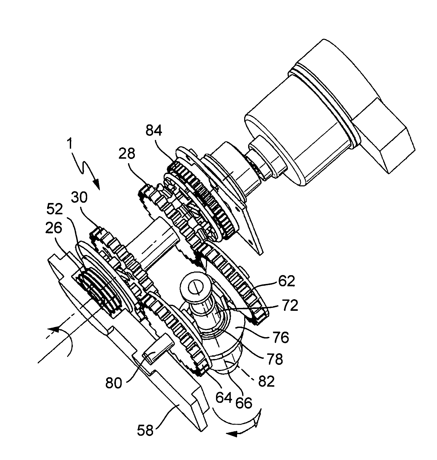
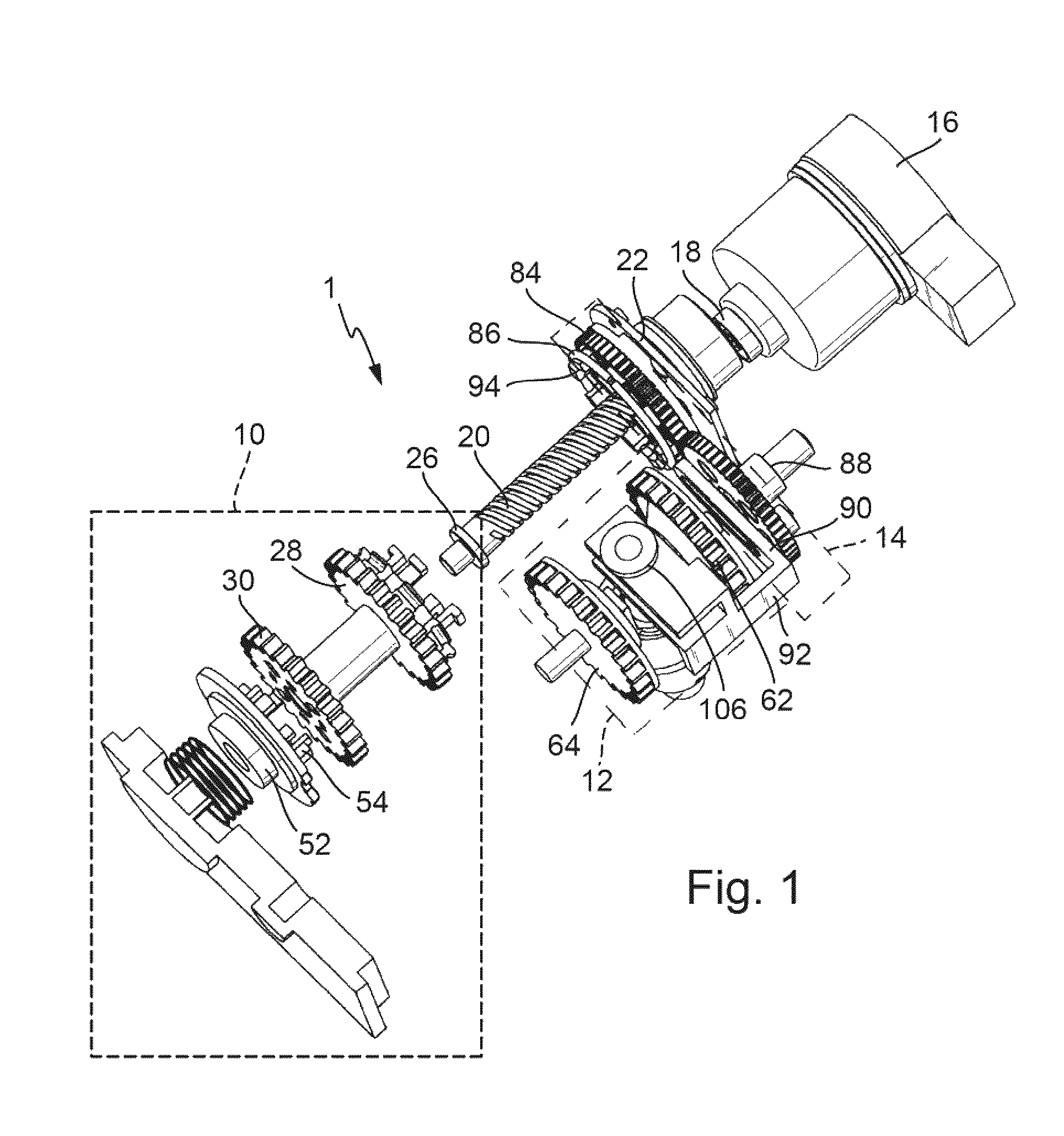
[0014]FIG. 1 shows a three-dimensional exploded view of an exemplary single motor transmission shifting mechanism 1, or a single motor transmission shifting unit 1 in a schematic view. The single motor transmission shifting mechanism 1 consists of three modules 10, 12, 14, or comprises three modules 10, 12, 14. First module 10 of these three modules 10, 12, 14 is a select shift switching mechanism; a second one of the modules 10, 12, 14 is shifting mechanism 12; third module 14 of these three modules 10, 12, 14 is gear selecting mechanism 14. The single motor transmission shifting mechanism 1 furthermore comprises one, or exactly one electric motor 16. Together with electric motor 16, or exactly one electric motor 16, the three components, or modules 10, 12, 14 for selecting and shifting gears in a transmission that is not shown, or in a motor vehicle transmission device, can be used.

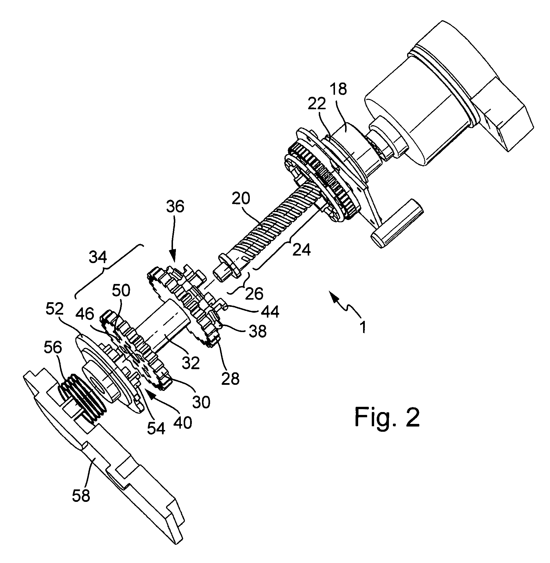
[0015]FIG. 2 shows a three-dimensional exploded view of the exemplary transmission shifting mechanis...


PUM


Abstract

A single motor transmission shifting mechanism with exactly one electric motor for generating drive motions for selecting, and for generating drive motions for shifting gears of a motor vehicle transmission device, and with a threaded spindle for switching from a mode, in which selection motions can be effectuated, into a mode, in which shifting motions can be effectuated, and with a shifting shaft, which can be moved in axial direction for selecting, and which can be rotated around its longitudinal axis for shifting, wherein all components, transferring the drive load for shifting from the electric motor to the shifting shaft during shifting operation, maintain their axial position relative to the longitudinal axis of the threaded spindle during this shifting operation.

Description

CROSS REFERENCE TO RELATED APPLICATIONS[0001]This application claims the benefit under 35 U.S.C. §119(e) of U.S. Provisional Application No. 60 / 843,039, filed Sep. 8, 2006, which application is incorporated herein by reference.FIELD OF THE INVENTION[0002]The invention relates to a single motor shifting mechanism for a motor vehicle transmission.BACKGROUND OF THE INVENTION[0003]Conventional shifting mechanisms, through which shifting motions were accomplished through electric motors, were provided, so that an electric motor was provided for generating selection motions, and an electric motor was provided for generating shifting motions. Meanwhile, however, also transmission shifting mechanisms are known, which only have one, or exactly one, electric motor, through whose drive motions, actuating motions for selecting and also actuating motions for shifting gears can be caused. Transmission shifting mechanisms of the latter kind are also called single motor transmission shifting mechan...

Claims


Application Information

Patent Timeline
Patent Type & Authority Patents(United States)
IPC IPC(8): F16H59/00B60K17/04F16H3/34
CPCF16H61/32F16H63/20F16H2061/2884Y10T74/2003F16H2061/2876Y10T74/19251Y10T74/19358F16H2061/2838
Inventor JAYARAM, MAVINKALMCCONNELL, TREVOR
Owner SCHAEFFLER TECH AG & CO KG
Why Eureka
Try Eureka