Axial anti-rotation coupling

a coupling and axial technology, applied in the direction of coupling device connection, coupling parts engagement/disengagement, electrical apparatus, etc., can solve the problems of adding to the complexity and cost of the connector, and achieve the effect of simple and low cost mechanism, high and low resistance to nut rotation

Inactive Publication Date: 2010-12-07
ITT MFG ENTERPRISES LLC
View PDF13 Cites 32 Cited by
  • Summary
  • Abstract
  • Description
  • Claims
  • Application Information

AI Technical Summary

Benefits of technology

[0002]In accordance with one embodiment of the invention, an electrical connector is provided which has a coupling nut rotatable about a barrel, around a connector axis that extends in forward and rearward directions. The connector also has a simple and low cost mechanism for regulating resistance to nut rotation. The mechanism provides low resistance to nut rotation in a first direction for mating to another connector, and provides a higher resistance to nut rotation in an opposite second direction for unmating.
[0004]The control washer rear locations are bent into loops that form rearward projections that press against the circle of teeth. The washer has ears that extend radially outward into slots formed in the nut, to prevent rotation of the washer. The control washer replaces the plurality of parts previously used, to reduce cost of manufacture and cost of installation.

Problems solved by technology

The need for two or three different parts that each must be mounted, adds to the complexity and cost of the connector.

Method used


Image

  • Axial anti-rotation coupling
  • Axial anti-rotation coupling
  • Axial anti-rotation coupling

Examples


Embodiment Construction

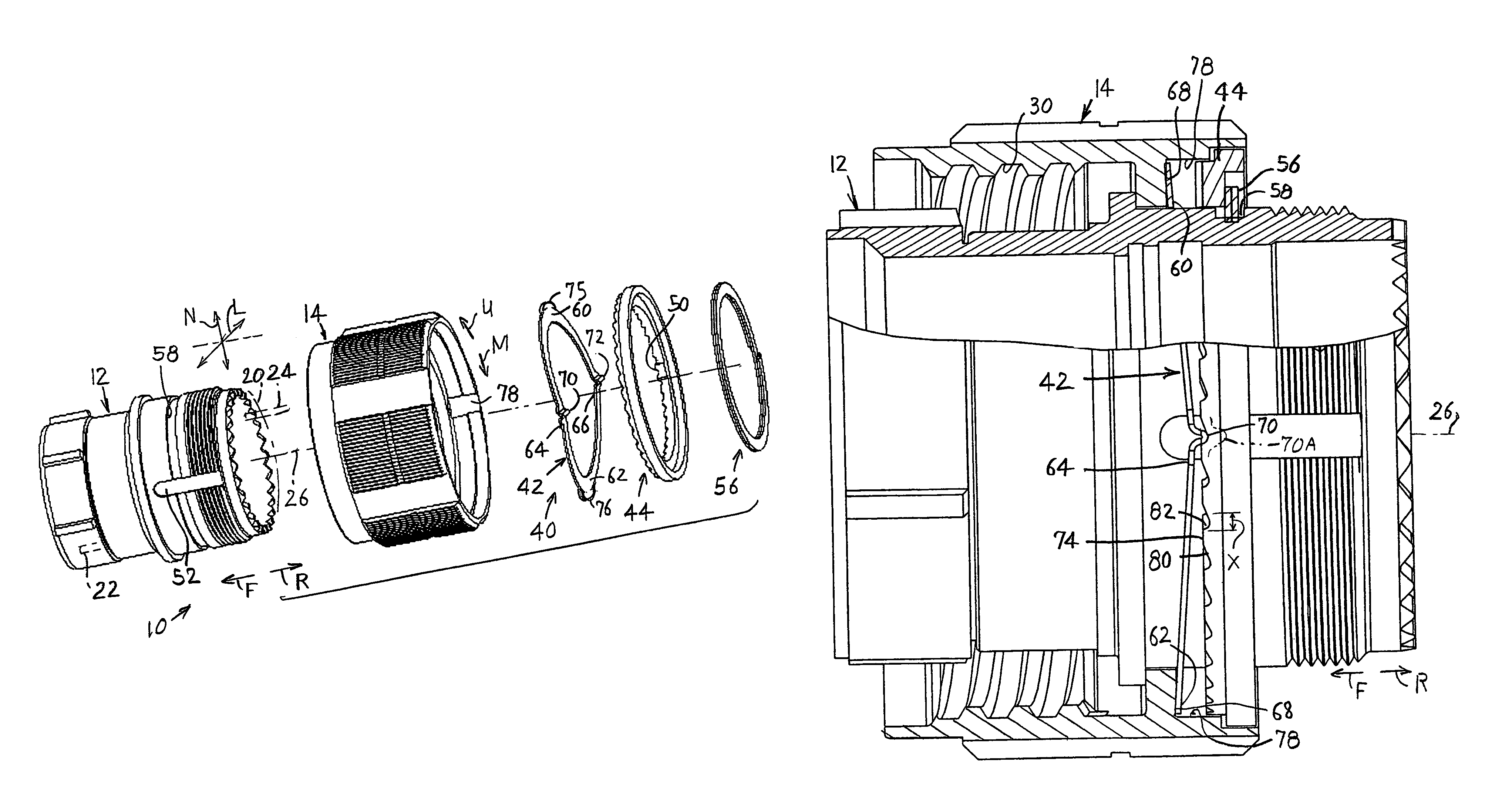
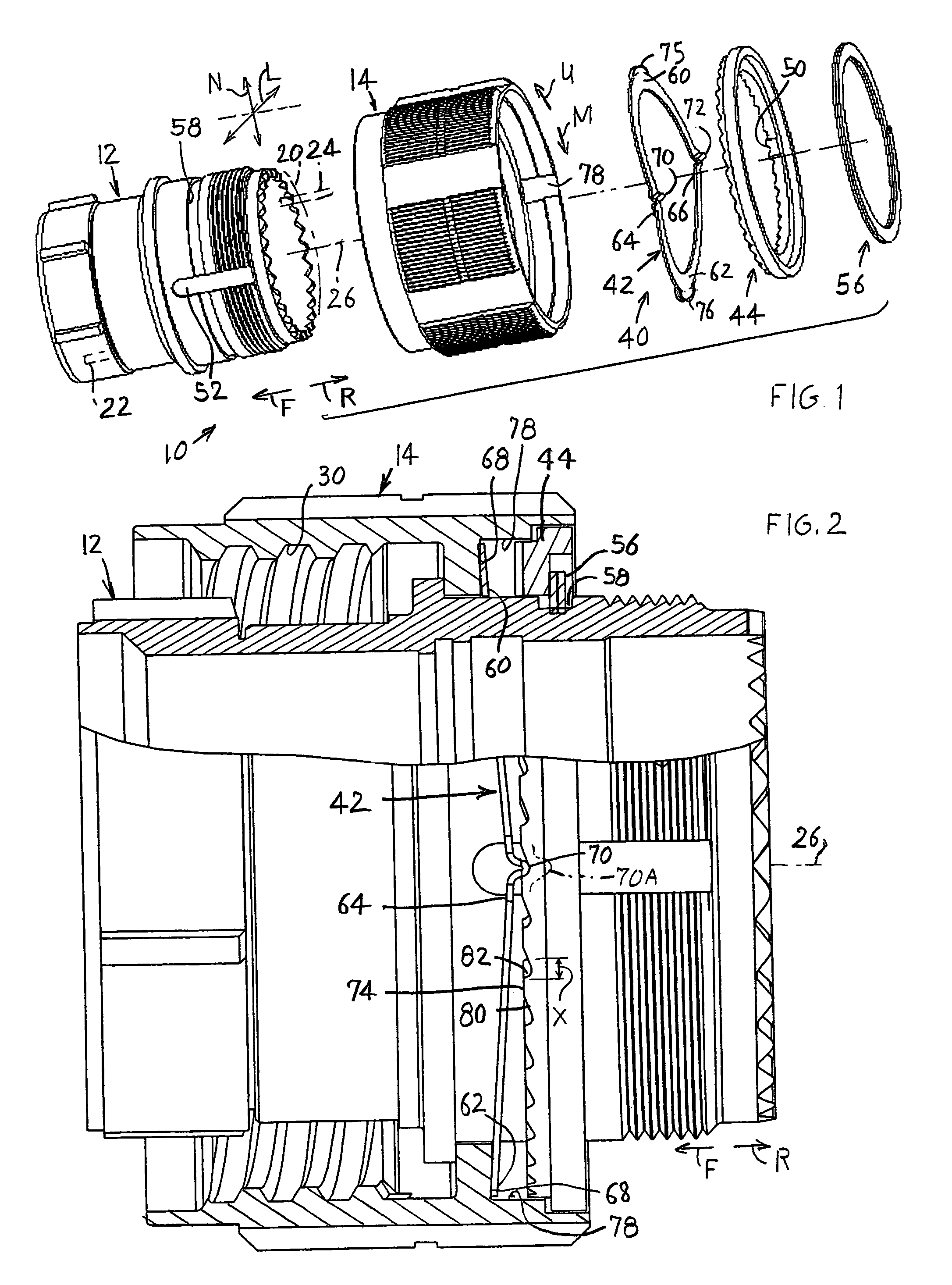
[0012]FIGS. 1 and 2 show an electrical connector 10 of the present invention which includes a barrel element 12 and a coupling nut element 14. The barrel 12 is used to mount a dielectric body 20 that holds contacts 22 and wires 24. The connector has a connector axis 26. The nut 14 is rotatable by hand about the barrel, and the nut has internal threads 30 that receive a threaded mating connector (not shown) to mate thereto. During mating, the nut 14 is turned in a mating direction M to advance the connector 10 in a mating, or forward F direction, and during unmating the nut is turned in the unmating direction U to move the connector in the unmating, or rear direction R.

[0013]It is desirable to provide moderate resistance to turning of the coupling nut during mating. However, it is desirable to provide a much higher resistance to turning of the nut during unmating to prevent unintentional nut turning and corresponding unintentional unmating of the connectors. The connector includes a ...


PUM


Abstract

A mechanism of low cost and easy mounting, provides resistance to rotation of a coupling nut (14) of an electrical connector about the barrel (12) of the connector, and provides a higher resistance to rotation in one direction (U) than the opposite direction (M). A toothed ring (44) with a circle of teeth, is fixed to the barrel. The mechanism includes a washer (42) with projections (70, 72) that engage the teeth of the ring to ride over them during nut rotation, and thereby provide resistance to nut rotation. The washer is bent to form a spring to bias its projections against the teeth of the toothed ring. The washer also has ears (75, 76) that fit into slots in the nut to prevent washer rotation relative to the nut. The teeth of the toothed ring have first sides that are steeper than its second sides to provide higher resistance to rotation in one direction.

Description

BACKGROUND OF THE INVENTION[0001]One type of electrical connector includes a barrel on which is mounted an insulative body with passages that hold wires and contacts. A coupling nut is rotatably mounted on the barrel so the nut can be rotated to thread it onto a mating second connector that has mating contacts. It is usually desirable to allow nut rotation with only a moderate resistance in a first direction to move the connectors together to mate, and to provide a much higher resistance to nut rotation in the opposite second direction to move the connectors apart to unmate. One type of mechanism includes a ring with projections for engaging a ring of teeth on the barrel, and a wave spring that biases the ring and its projections against the teeth. Pins extending thorough the ring prevent its rotation relative to the barrel. The need for two or three different parts that each must be mounted, adds to the complexity and cost of the connector.SUMMARY OF THE INVENTION[0002]In accordanc...

Claims


Application Information

Patent Timeline
Patent Type & Authority Patents(United States)
IPC IPC(8): H01R4/38
CPCH01R13/622H01R13/639
Inventor GASTINEAU, DOUGLAS REID
Owner ITT MFG ENTERPRISES LLC
Why Eureka
Try Eureka