Duty detecting circuit and duty cycle corrector including the same

a duty cycle and circuit technology, applied in pulse generators, pulse manipulation, pulse techniques, etc., can solve the problems of increasing the locking time, the difficulty of digital duty cycle correctors in measuring an accurate duty ratio, and many limitations of conventional duty cycle correctors in correcting the clock duty cycle. , to achieve the effect of reducing the locking tim

Active Publication Date: 2010-12-07
SK HYNIX INC
View PDF14 Cites 20 Cited by
  • Summary
  • Abstract
  • Description
  • Claims
  • Application Information

AI Technical Summary

Benefits of technology

[0009]Embodiments of the present invention are directed to provide a duty cycle corrector which is capable of reducing a locking time, exactly correcting a duty cycle, and correcting duty cycles of clocks having various frequencies.

Problems solved by technology

Conventional duty cycle correctors have many limitations in correcting the clock duty cycle.
Such duty cycle correctors perform several comparison operations until completion of the duty cycle correction, which will increase a locking time.
Second, digital duty cycle correctors have difficulty in measuring an accurate duty ratio because of their own offset.
Third, there is a limitation in a frequency range of an input clock whose duty cycle will be corrected.

Method used


Image

  • Duty detecting circuit and duty cycle corrector including the same
  • Duty detecting circuit and duty cycle corrector including the same
  • Duty detecting circuit and duty cycle corrector including the same

Examples


Embodiment Construction

[0023]Other objects and advantages of the present invention can be understood by the following description, and become apparent with reference to the embodiments of the present invention.

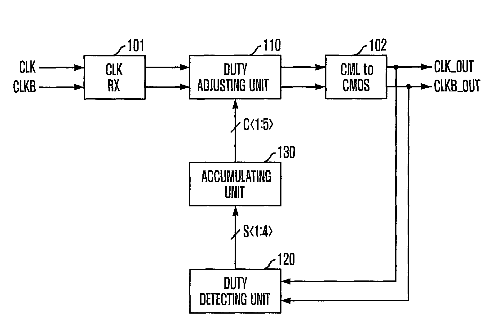
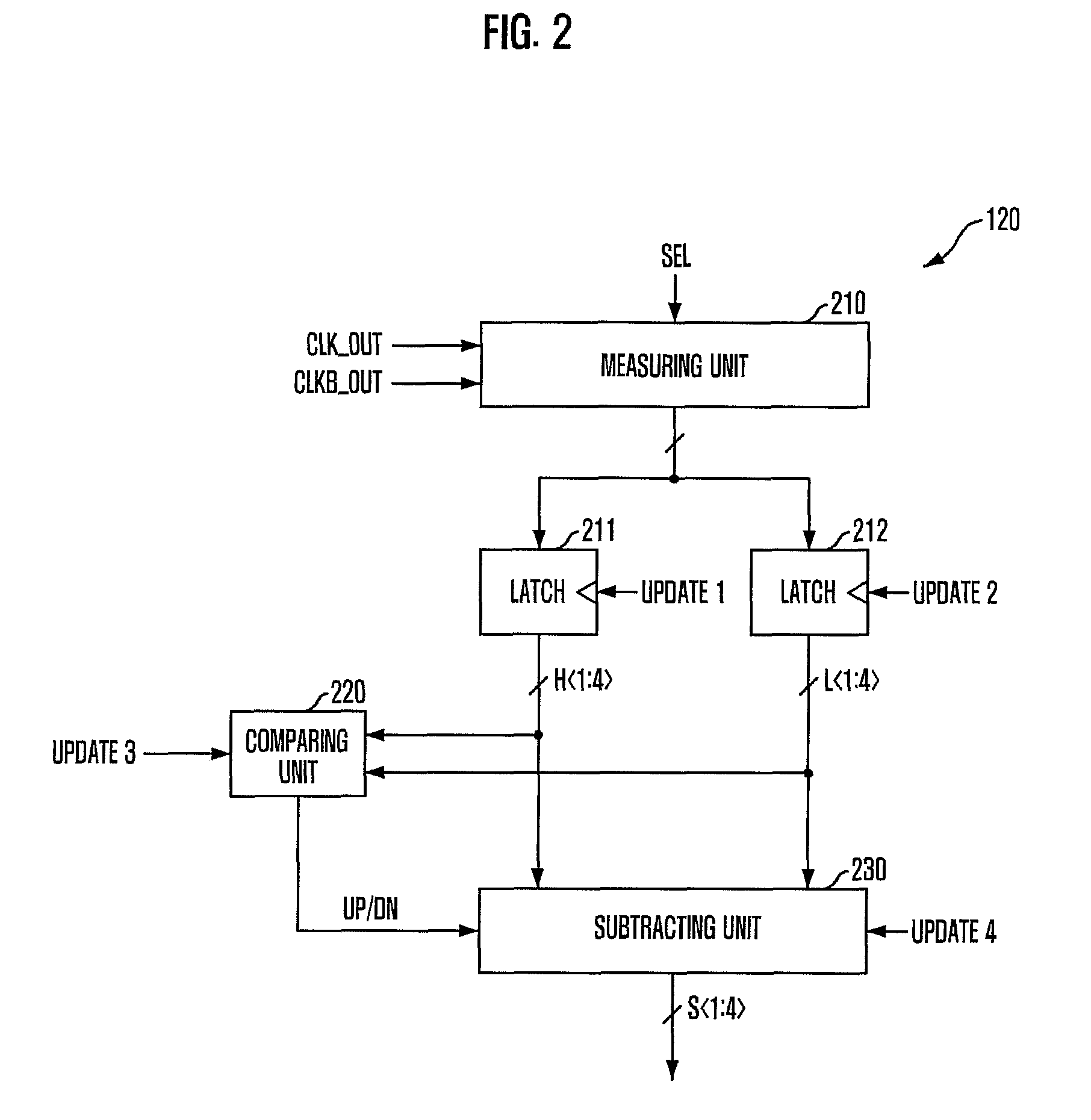
[0024]FIG. 1 is a block diagram of a duty cycle corrector in accordance with an embodiment of the present invention.

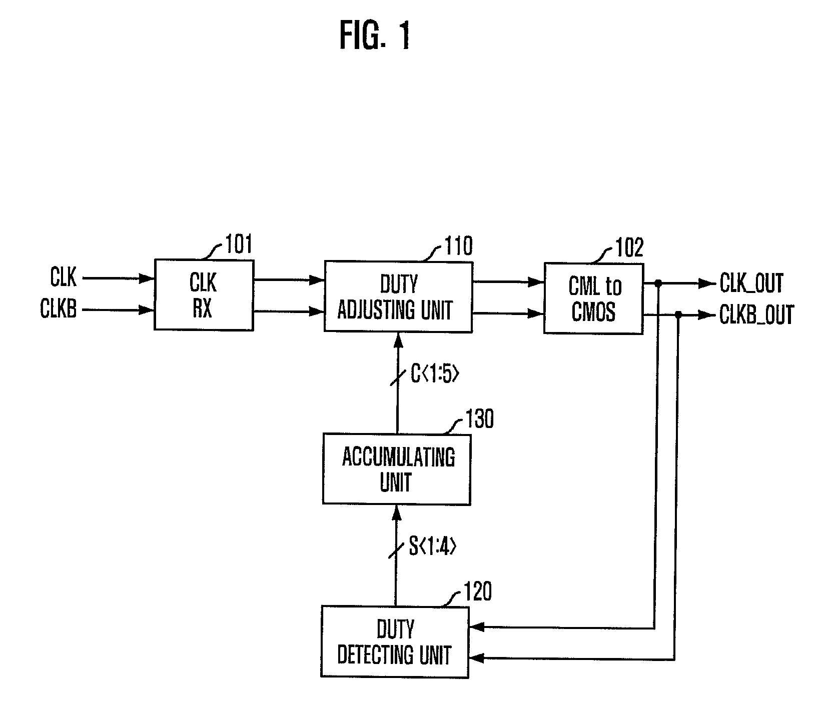
[0025]Referring to FIG. 1, the duty cycle corrector in accordance with the embodiment of the present invention includes a duty adjusting unit 110, a duty detecting unit 120, and an accumulating unit 130. The duty adjusting unit 110 adjusts duty cycles of input clocks CLK and CLKB in response to a duty correction code C to generate output clocks CLK_OUT and CLKB_OUT. The duty detecting unit 120 measures a difference between a high pulse width and a low pulse width of the output clocks CLK_OUT and CLKB_OUT to output difference values S. The accumulating unit 130 accumulates the difference values S to generate the duty correction code C.

[0026]To be specific, the duty detecting unit 120 me...


PUM


Abstract

A duty cycle corrector includes a duty adjusting unit configured to adjust a duty cycle of an input clock in response to a duty correction code and generate an output clock, a duty detecting unit configured to measure a difference between a high pulse width and a low pulse width of the output clock and output a difference value, and an accumulating unit configured to accumulate the difference value to generate the duty correction code.

Description

CROSS-REFERENCE TO RELATED APPLICATION[0001]The present invention claims priority of Korean patent application number 10-2008-0108994, filed on Nov. 4, 2008, which is incorporated by reference in its entirety.BACKGROUND OF THE INVENTION[0002]The present invention relates to a duty detecting circuit and a duty cycle corrector including the same, and more particularly, to a technology that can exactly measure a duty distortion degree at a time.[0003]In semiconductor devices such as semiconductor memory devices designed to operate based on a clock, it is very important to exactly control a duty cycle of the clock. A 50% clock duty ratio means that a “high” level period is equal to a “low” level period in the clock.[0004]A semiconductor memory device must input and output data exactly in synchronization with rising and falling edges of the clock. If the clock duty ratio is not exactly 50%, a timing between the rising edge and the falling edge is distorted so that data are not outputted ...

Claims


Application Information

Patent Timeline
Patent Type & Authority Patents(United States)
IPC IPC(8): H03K7/08
CPCH03K5/1565H03K5/159H03K5/26H03K5/153H03K5/19
Inventor SHIN, DONG-SUK
Owner SK HYNIX INC
Why Eureka
Try Eureka