Two terminal variable resistor

a resistor and terminal technology, applied in the field of resistors, potentiometers or rheostats, can solve problems such as definite disadvantages

Inactive Publication Date: 2010-12-07
GERFAST STEN R
View PDF8 Cites 1 Cited by
  • Summary
  • Abstract
  • Description
  • Claims
  • Application Information

AI Technical Summary

Benefits of technology

[0009]It is varying the resistance between its two electrical terminals by increasing or decreasing the contact area between two conductive strips in parallel.
[0050]Embodiment “B” lends itself very well to usage as a variable capacitor, increasing and decreasing the capacity when the actuator varies the distance between the two strips. If the two strips also had a layer of resistive coating it would function as a “variable capacitor and variable resistance at the same instant” type of device. When the capacitance goes up, the capacitive reactance and the resistance goes up at the same time. It could possibly be used in an R / C network.

Problems solved by technology

The potentiometer with the safety resistor of course prevents the usage of varying the resistance down to lower readings; a definite disadvantage.
The above limitations of related art potentiometers are described when varying current in a DC circuit, but if it is used for AC operation, other restrictions such as peak voltage versus R.M.S. voltage have to also be considered.
The linear type is also a 3 terminal device with two fixed terminals and a wiper manipulated by a sliding handle, with the same inherent problems as above.

Method used


Image

  • Two terminal variable resistor
  • Two terminal variable resistor

Examples


Embodiment Construction

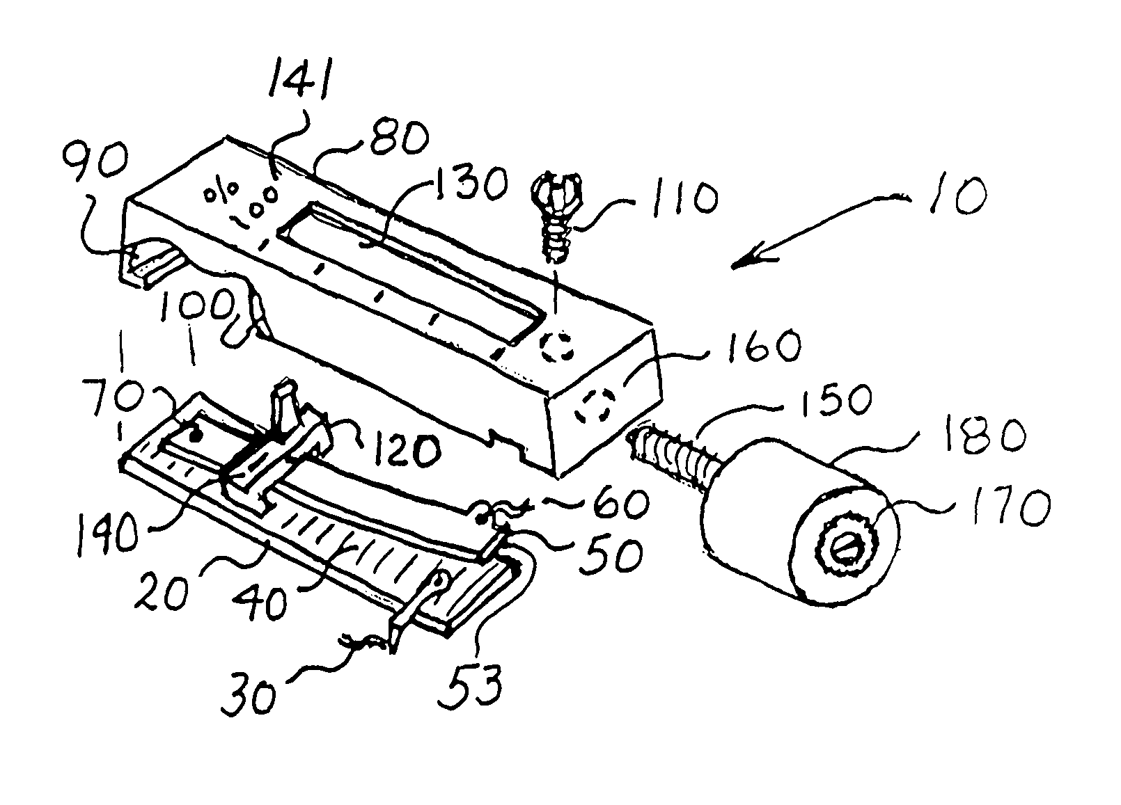
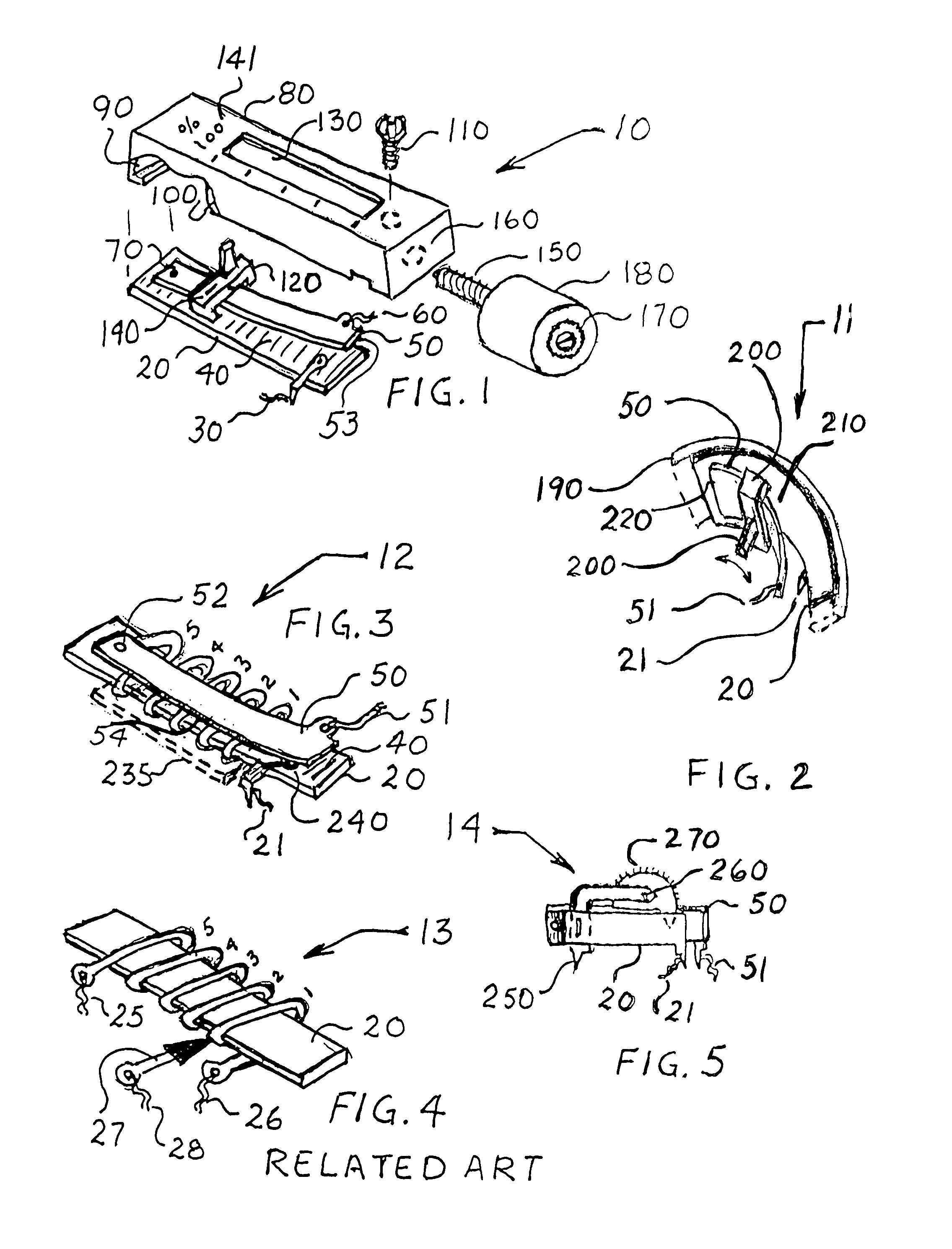
[0070]FIG. 1 is a composite drawing as an exploded view of variable resistors in differing embodiments. When similar parts are used in different figures, the reference numbers on these similar parts are given the same reference numbers.

[0071]The first description is of the smallest, simplest and least expensive variable resistor assembly 10 of the present invention. It has a first strip 20 with an electrical connection 30 also connected to a coating 40, a second resilient strip 50 with electrical connection 60 and a conductive coating 53 on the side facing the first strip 20, with both strips connected together at 70.

[0072]Strip 20 and strip 50 are also mounted together on frame 80 with a snap-fit 90 shown towards the broken out section 100.

[0073]A simple actuator screw 110 is shown in a position to be able to decrease spacing between the “V” shaped” assembly of strip 20 and strip 50.

[0074]FIG. 1 is a second description that is also a view of basically the same variable resistor ass...


PUM


Abstract

A small inexpensive two terminal variable resistance assembly that conveniently changes its resistance when a force of an actuator is applied. It can be made for power applications as well as in miniature dimension versions in values from milli-ohms to meg-ohms.This variable resistor increases its power handling capacity during a decrease in its ohmic value, contrary to present three terminal potentiometers or reostats. It does this by a rolling action that increases or decreases two resistive surface areas in parallel. It could also be used as a variable capacitor.

Description

FIELD OF THE INVENTION[0001]This invention relates to resistors, potentiometers or rheostats that varies their value when actuated. It is small inexpensive two terminal variable resistor that can be used wherever resistive values have to be varied in electronic circuitry or electrical devices.[0002]It can be made for power applications as well as in miniature dimension versions from milli ohm to mega ohm values. It does this by a rolling action that increases or decreases two resistive surface areas in parallel. This paralleling increases its power handling capability towards its lower ohms settings, contrary to present three terminal potentiometers.[0003]It could also be used as a variable capacitor.BACKGROUND[0004]The present inventions two terminal variable resistor increases its power-handling-capacity during a decrease in its numerical ohm value, contrary to present potentiometers or rheostats, that decrease their power capability with decreasing numerical ohm values. Related a...

Claims


Application Information

Patent Timeline
Patent Type & Authority Patents(United States)
IPC IPC(8): H01C10/12
CPCH01C10/42
Inventor GERFAST, STEN R.
Owner GERFAST STEN R
Why Eureka
Try Eureka