Method for transmitting synchronization messages in a communication network

a communication network and synchronization message technology, applied in the field of communication network synchronization message transmission in the communication network and the corresponding communication network, can solve the problems of incorrect determination of the pulse counter status of the synchronization clock in the individual network nodes, imprecise synchronization of the internal clock of the network nodes, etc., and achieve the effect of precise synchronization of the individual internal clocks

Active Publication Date: 2010-12-07
SIEMENS AG
View PDF10 Cites 6 Cited by
  • Summary
  • Abstract
  • Description
  • Claims
  • Application Information

AI Technical Summary

Benefits of technology

[0006]An object of the invention is therefore to create a method for transmitting synchronization messages in a communication network, which allows precise synchronization of the individual internal clocks of the network nodes.
[0010]The inventive approximation of the behavior over time of the pulse ratio using a function takes into account a change in the pulse ratio due to a change in the synchronization clock frequency and / or the node clock frequency when determining the pulse counter status. In particular the pulse ratio at the time of transmission of the synchronization message to the next network node can be predicted using the function, thereby achieving significantly more precise determination of the current pulse counter status.
[0012]In one embodiment of the inventive method the approximated pattern over time of the pulse ratio is used to determine the pulse ratio at the time of transmission of a synchronization message at the preceding network node, this pulse ratio in combination with the predefined time delay being used to determine the number of synchronization pulses between transmission of the synchronization message at the preceding network node and transmission of the synchronization message at the respective network node. The pulse ratio is therefore assumed to be constant between transmission of the synchronization message at the preceding network node and transmission of the synchronization message at the respective network node. This does not always correspond to actual circumstances but it has proven that the resulting error is very small. One advantage of this variant is the simple calculation of the number of synchronization pulses within the predefined time delay, which can in particular be determined by multiplying the pulse ratio, which is assumed to be constant, by the time delay.
[0017]As can be seen from the detailed description in the application, it is possible with the above linear function RCF(t) to avoid errors in the determination of the pulse counter status in the event of a linear change in the pulse ratio.
[0018]In some instances instead of a linear function a polynomial function can also be used to approximate the pattern over time of the pulse ratio. This can increase the accuracy of the method in the event of non-linear changes in the pulse ratio.

Problems solved by technology

It is problematic here that fluctuations can occur in the synchronization clock frequency, which result in an imprecise estimation of the pulse ratio and therefore incorrect determination of the pulse counter status of the synchronization clock in the individual network nodes.
As set out above it is problematic with the communication networks known from the prior art that when the synchronization clock frequency of the synchronization clock is changed, errors occur in the determination of the pulse counter status in the network nodes, which in turn results in imprecise synchronization of the internal clocks of the network nodes.

Method used


Image

  • Method for transmitting synchronization messages in a communication network
  • Method for transmitting synchronization messages in a communication network

Examples


Embodiment Construction

[0031]The inventive method is preferably deployed in an industrial automation system, in which distributed components of the system communicate with one another, to control manufacturing sequences, e.g. in automobile production. To this end the individual components communicate with one another wirelessly and / or wired by way of a communication network. The components thus represent network nodes of the communication network.

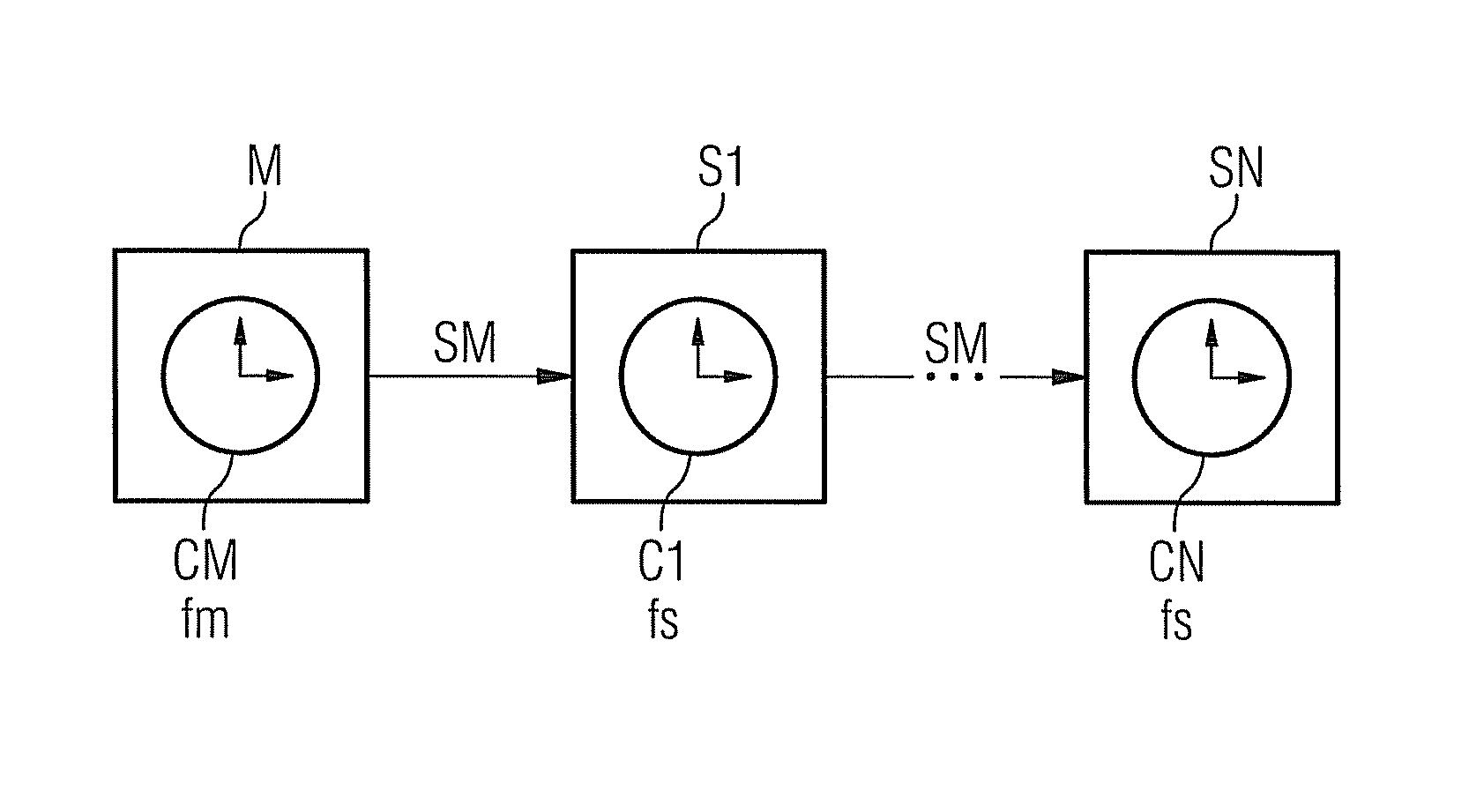
[0032]In the embodiment according to FIG. 1 so-called slaves S1 to SN are shown by way of example as network nodes, each slave having a corresponding internal clock C1, . . . , CN. Each of these clocks operates at a predefined slave clock frequency fs, which can in some instances be different for different slaves. A so-called master element M is also provided in the communication network in FIG. 1, having a synchronization clock CM, which predefines a synchronization clock frequency fm, to which all the internal clocks C1, . . . , CN of the slaves are to be set. ...


PUM


Abstract

There is described a method for transmitting synchronization messages in a communication network, the communication network comprising a plurality of network nodes communicating with one another, each containing an internal clock, which is timed with a node clock frequency assigned to the respective network node. The synchronization messages transmitted in the communication network serve to synchronize the times of the internal clocks of the network nodes and contain the pulse counter status of a synchronization clock operating at a predefined synchronization clock frequency. The pulse counter status is estimated by each network node and updated in the synchronization message. Changes in the synchronization clock frequency are taken into account when estimating the pulse counter status. Precise determination of the pulse counter status is achieved with the aid of an approximation of the change over time in the pulse ratio between synchronization clock frequency and node clock frequency by means of a function, with the result that the pulse ratio on transmission of a new synchronization message can be predicted and a precise current pulse counter status can be determined on the basis of the predicted pulse ratio. The method is particularly suitable for use in a communication network of an industrial automation system, whose components communicate with one another for example according to the Profinet standard.

Description

CROSS REFERENCE TO RELATED APPLICATIONS[0001]This application claims priority of European Patent Office application No. 07017615.1 EP filed Sep. 7, 2007, which is incorporated by reference herein in its entirety.FIELD OF INVENTION[0002]The invention relates to a method for transmitting synchronization messages in a communication network and a corresponding communication network.BACKGROUND OF INVENTION[0003]Communication networks are used in a very wide range of areas to control work sequences in a decentralized manner. In industrial automation systems in particular it is particularly important for the automatic work processes to be coordinated with one another. This is achieved in that the individual communicating network nodes in the communication network have internal clocks, with synchronization messages being transmitting to synchronize all the internal clocks. The internal clock of a respective network node hereby operates at a corresponding node clock frequency, which may in s...

Claims


Application Information

Patent Timeline
Patent Type & Authority Patents(United States)
IPC IPC(8): H04J3/06
CPCH04J3/0664H04J3/0673
Inventor GOTZ, FRANZ-JOSEFNA, CHONGNINGOBRADOVIC, DRAGANSCHEITERER, RUXANDRASTEINDL, GUNTER
Owner SIEMENS AG
Why Eureka
Try Eureka