Engine head structure

a technology of engine head and cylinder head, which is applied in the direction of electric ignition installation, machines/engines, mechanical equipment, etc., can solve the problems of difficult to further assemble the mounting structure of the pressure sensor in the cylinder head, failure in combustion and ignition detection, and complex mounting structure of the pressure sensor, etc., to achieve easy assembling and simplified structure of the engine head modul

Inactive Publication Date: 2010-12-14
DENSO CORP
View PDF23 Cites 40 Cited by
  • Summary
  • Abstract
  • Description
  • Claims
  • Application Information

AI Technical Summary

Benefits of technology

[0007]It is an object of the present invention to provide an engine head structure, in which a pressure sensor for detecting pressure inside a cylinder room of an engine can be disposed easily and its assembling structure can be simplified.
[0009]In the above configuration, because the pressure sensor for detecting pressure inside the cylinder room of the engine is disposed integrally in the common housing together with the injector and the spark plug, the pressure sensor can be attached easily to the cylinder head without being directly bonded to the cylinder head. Thus, the pressure sensor can be disposed easily while the assembling structure of the engine head module can be simplified.

Problems solved by technology

Recently, it is considered that failure in combustion and ignition is detected by a pressure sensor for detecting pressure inside a cylinder room of the engine.
Because an inlet valve, an outlet valve, an injector and a spark plug or the like are disposed in the cylinder head, it is difficult for the pressure sensor to be further disposed in the cylinder head due to space limitations.
Thus, the mounting structure of the pressure sensor may become complex.
In addition, by welding a small element such as the pressure sensor to a large element such as the cylinder head, a large welding apparatus may be required, the workability of assembling may be decreased, and the manufacturing cost may be increased.

Method used


Image

  • Engine head structure
  • Engine head structure
  • Engine head structure

Examples


Embodiment Construction

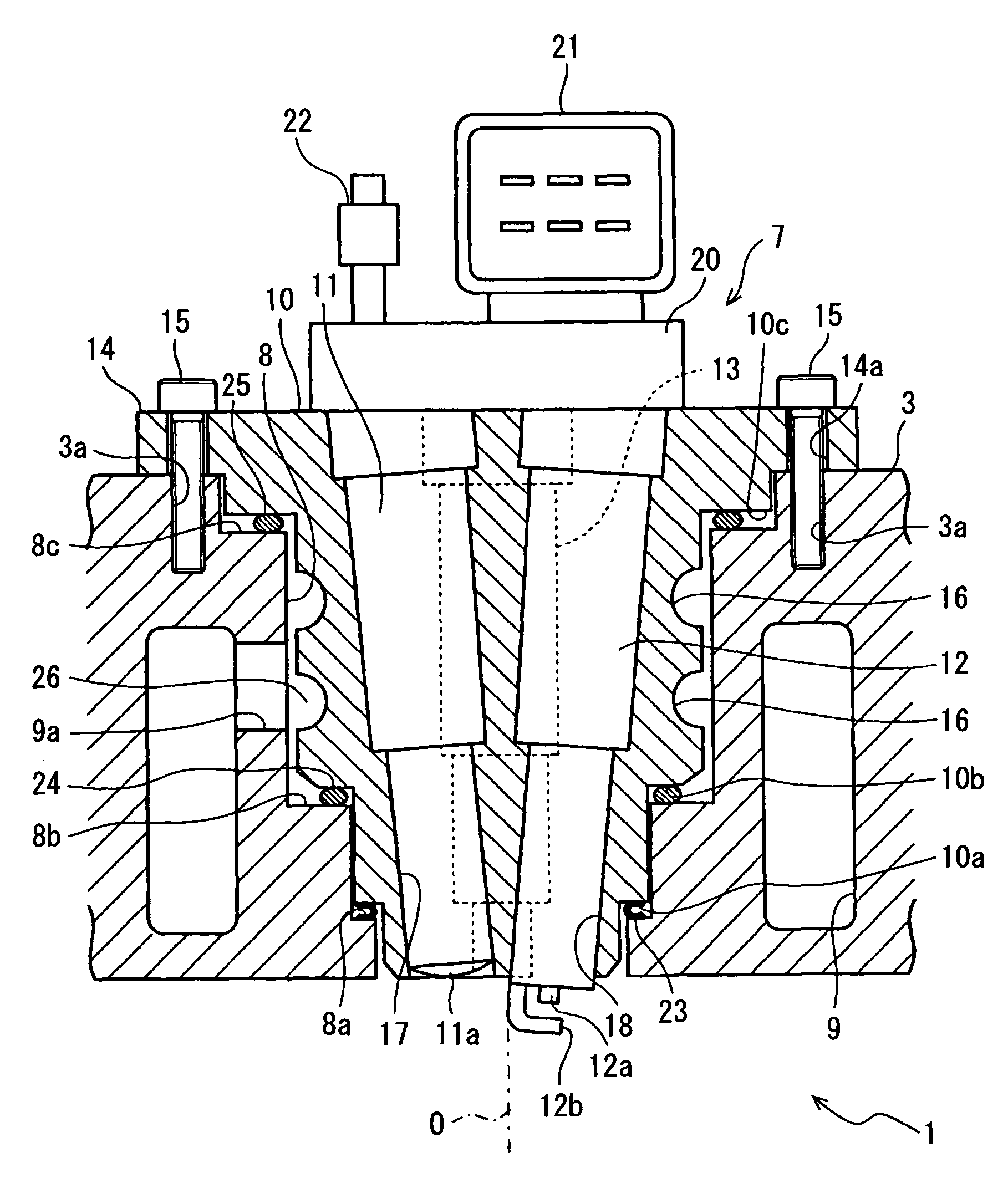
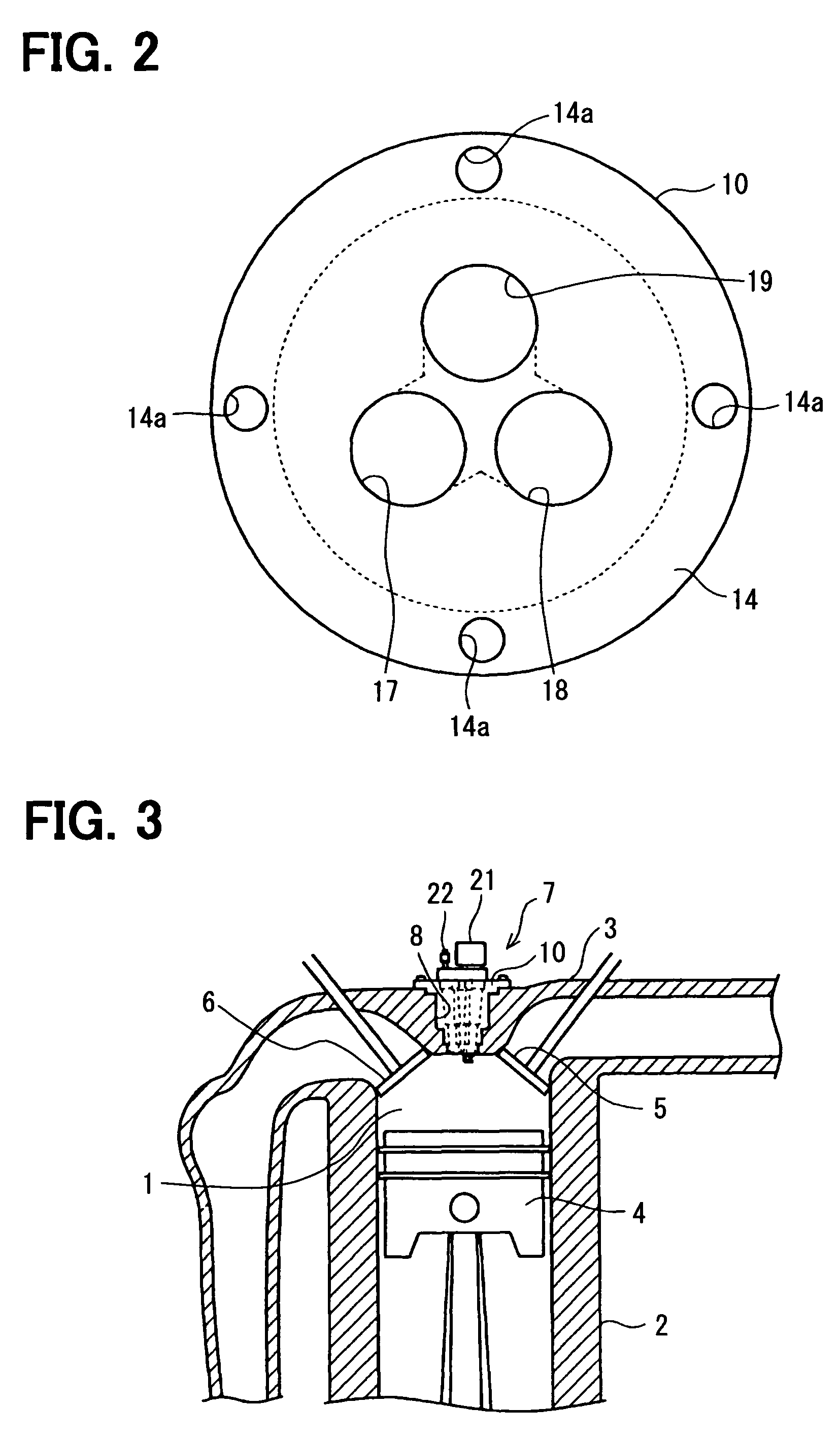
[0014]Hereinafter, an embodiment of the present invention will be described with reference to FIG. 1 to FIG. 3. FIG. 3 shows an engine head module 7 located at an upper portion of one cylinder room 1 of a vehicle engine, for example. The cylinder room 1 is configured by a cylinder block 2 and a cylinder head 3. Inside the cylinder room 1, a piston 4 is arranged to be movable upwardly or downwardly. A valve 5 for opening and closing an inlet, and a valve 6 for opening and closing an outlet are arranged at both sides of an upper part of the cylinder room 1. An engine head module 7, which is hereinafter referred to a module 7, according to the present embodiment is arranged between the inlet and the outlet. A plurality of the modules 7 are mounted respectively to the cylinders of the engine.

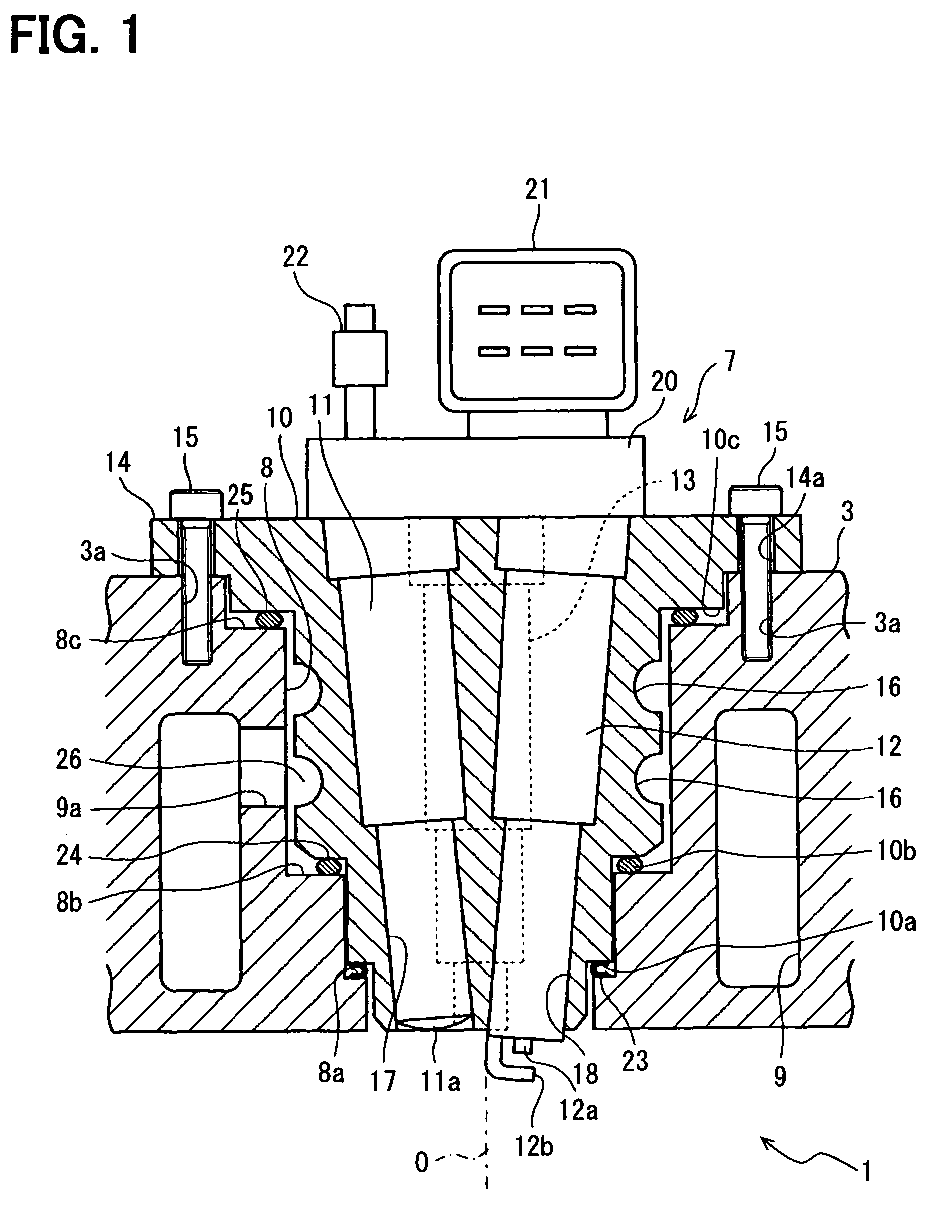
[0015]FIG. 1 shows a configuration and an assembling structure of the module 7 according to the present embodiment. A mounting hole 8, in which the module 7 is fixed, is formed at a center portion o...


PUM


Abstract

An injector, a spark plug and a pressure sensor are assembled integrally in a common housing. The common housing is fixed in a mounting hole provided in a cylinder head of an engine so that tip end portions of the injector, the spark plug and the pressure sensor face inside of the cylinder room. For example, a gasket having heat resistance can be provided between a lower end portion of an outer wall of the common housing and an inner wall of the mounting hole for the air-tight sealing. Furthermore, a concave portion may be provided at an outer portion of the common housing so as to form a coolant passage.

Description

CROSS REFERENCE TO RELATED APPLICATION[0001]The present application is based on Japanese Patent Application No. 2008-047726 filed on Feb. 28, 2008, the disclosure of which is incorporated herein by reference.FIELD OF THE INVENTION[0002]The present invention relates to an engine head structure with an engine head module for a cylinder head of an engine.BACKGROUND OF THE INVENTION[0003]A fuel direct-injection engine, e.g., a gasoline engine, of vehicles is disclosed in U.S. Pat. No. 6,055,955 corresponding to JP-A-2000-501816. The fuel direct-injection engine is configured such that a fuel injector and a spark plug are attached to a cylinder head of the engine.[0004]In an electric control system of this kind of vehicle engine, a fuel injection control and a spark timing control are performed by an ECU based on detection signals of multiple sensors for detecting states of the engine so that the engine is driven in an optimum condition. Recently, it is considered that failure in combust...

Claims


Application Information

Patent Timeline
Patent Type & Authority Patents(United States)
IPC IPC(8): F02M57/06F02M61/14
CPCF02F1/242F02M57/005F02M61/14F02M2200/858
Inventor TOYODA, INAO
Owner DENSO CORP
Why Eureka
Try Eureka