Waterproof method and construction for a wire end joint portion

a technology of wire end joints and waterproof methods, applied in the direction of insulating conductors/cables, coupling device connections, cables, etc., can solve the problems of deteriorating space efficiency, higher cost, and increase in mold production, so as to reduce the cost, prevent the increase of occupied space, suppress the effect of enlargemen

Active Publication Date: 2010-12-14
SUMITOMO WIRING SYST LTD
View PDF14 Cites 7 Cited by
  • Summary
  • Abstract
  • Description
  • Claims
  • Application Information

AI Technical Summary

Benefits of technology

[0014]According to the inventive waterproof method, the heat shrinkable tube continuously produced is used as a waterproof protection member instead of using a special molded protection cap. Thus, cost can be remarkably reduced. Further, if a plurality of sizes of heat shrinkable tubes are prepared and a heat shrinkable tube of the size conforming to the outer diameter of a wire end joint portion is selected and used, the heat shrinkable tube can be suitable for the outer diameter of the wire end joint portion in addition to the shrinkage of the heat shrinkable tube by a heating process. Therefore, enlargement and a resulting increase in installation space can be suppressed.
[0035]As is clear from the above description, the heat shrinkable tube is cut and used as the waterproof protection tube instead of using a special waterproof protection cap, which is molded, in the present invention. Thus, cost can be reduced. Further, since the diameter of the tube is narrowed through heat shrinkage, there are various advantages such as no need to use a large-diameter corrugated tube, particularly in the case of accommodating the wire end joint portion into a corrugated tube without excessively increasing an improvement of protection for the wire end joint portion.

Problems solved by technology

This necessitates many kinds of caps, leading to a cost increase for mold production and consequently leading to a higher cost.
Further, in the case of using a cap selected from those prepared beforehand, the outer diameter of the cap is larger than the wire end joint portion Y, thereby presenting a problem of deteriorating space efficiency.
Particularly, in the case of accommodating the wire end joint portion Y into a corrugated tube, a corrugated tube having a large inner diameter needs to be used, therefore leading to increases of cost and necessary space.
Further, if the inner diameter of the cap 1 increases, the amount of the waterproofing agent 2 to be injected also increases, leading to a cost increase also for the waterproofing agent 2.
However, there is a high possibility that the hot melt agent 3′ used as a sealing member is also melted upon heating the heat shrinkable tube for heat shrinkage, the hot melt adhesive 3 leaks out of the heat shrinkable tube 4 while the melted hot melt agent 3′ is cooled and solidified, and the wires W cannot be completely sealed without the hot melt agent 3′ fulfilling its function as the sealing member.
Further, if the hot melt agent 3 leaks out of the heat shrinkable tube 4, an operation becomes difficult to conduct for an operator.

Method used


Image

  • Waterproof method and construction for a wire end joint portion
  • Waterproof method and construction for a wire end joint portion
  • Waterproof method and construction for a wire end joint portion

Examples


Embodiment Construction

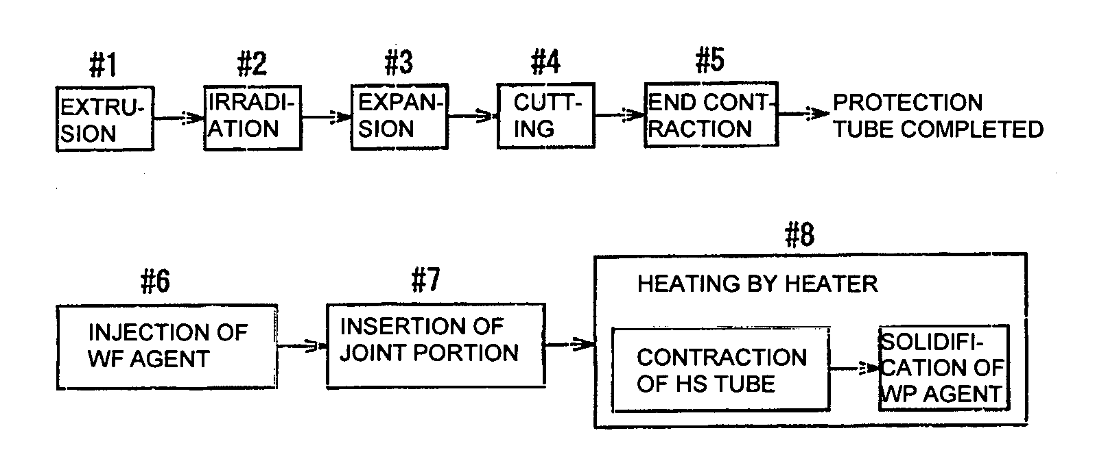
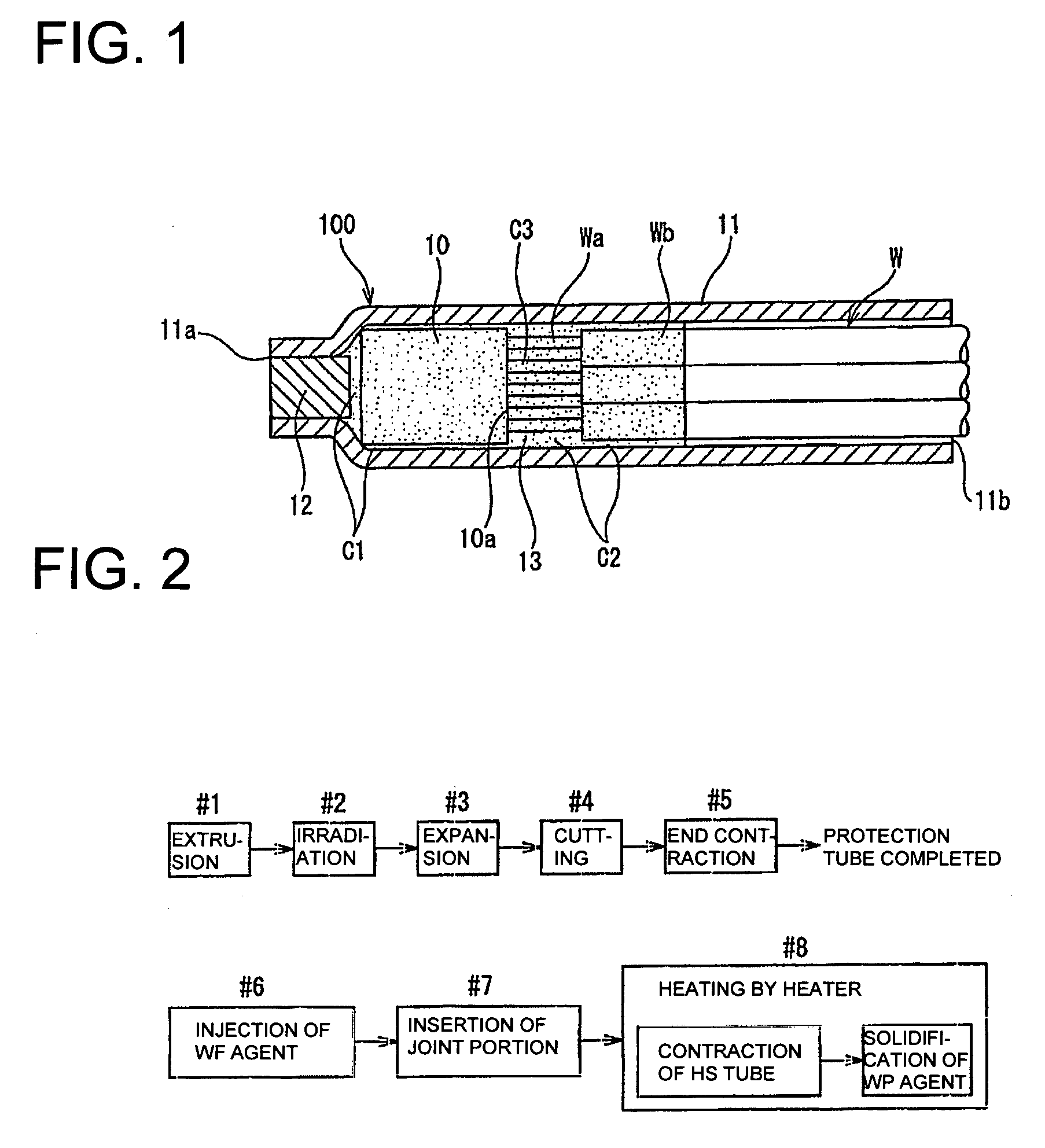
[0042]One embodiment of the present invention is described with reference to the accompanying drawings.

[0043]FIG. 1 shows a waterproof construction for a wire end joint portion formed by a method to be described later.

[0044]A wire end joint portion 10 is formed by integrally ultrasonic welding exposed parts Wa of cores at ends of a plurality of (three in this embodiment) wires w. It should be noted that resistance welding may be adopted instead of ultrasonic welding.

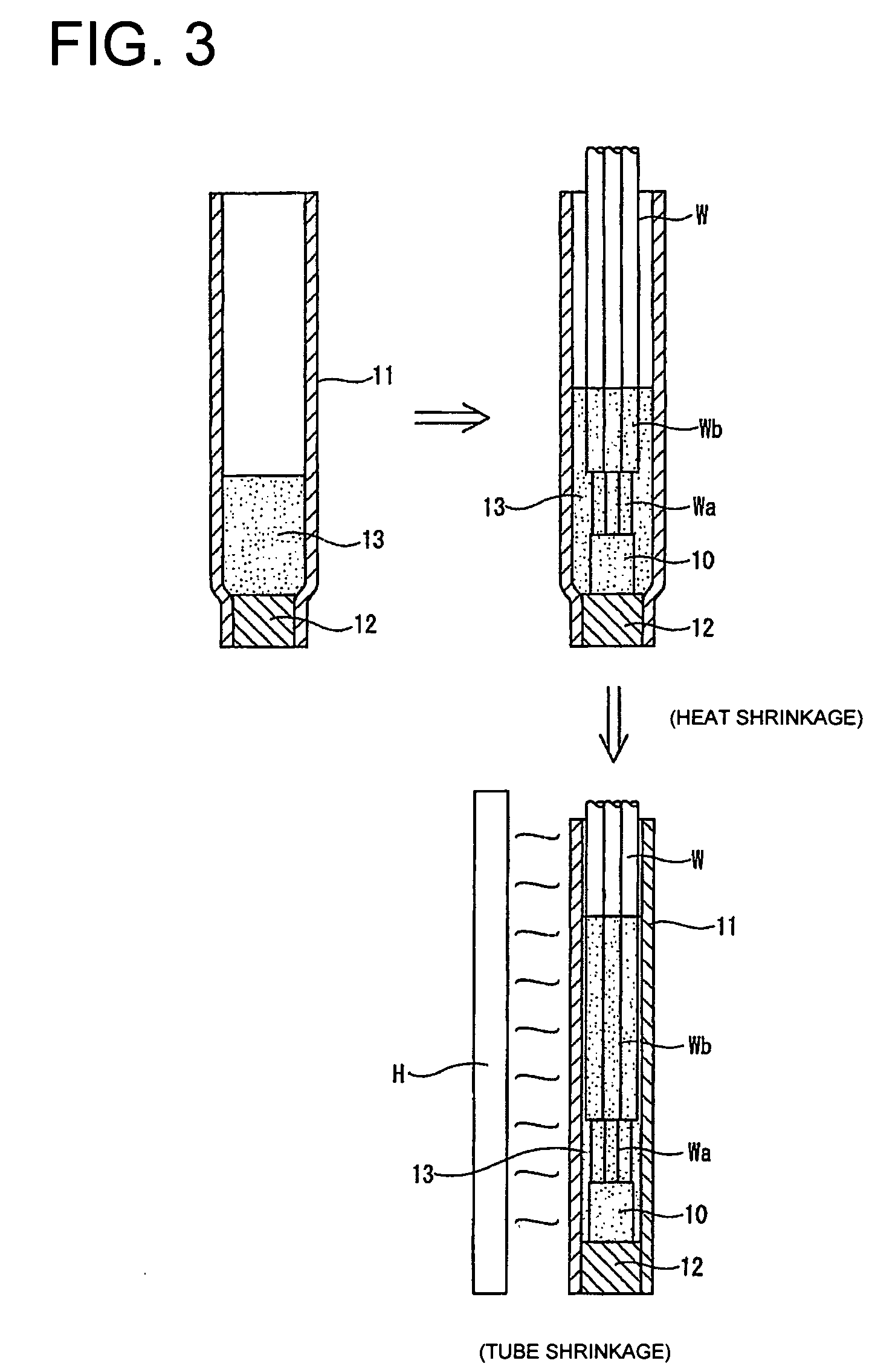
[0045]The wire end joint portion 10 is accommodated in a waterproof protection tube 100 comprised of a transparent heat shrinkable tube 11 cut to a desired length and a sealing member 12 for closing one end of the heat shrinkable tube 11.

[0046]The sealing member 12 is inserted through one end opening 11a of the heat shrinkable tube 11, and one end side 11a of the heat shrinkable tube 11, which becomes the outer circumference of the sealing member 12, is heat shrunk to adhere, whereby the heat shrinkable tube 11 is provid...


PUM

PropertyMeasurementUnit
temperatureaaaaaaaaaa
lengthaaaaaaaaaa

Abstract

A waterproof method for a wire end joint includes expanding a heat shrinkable tube radially outwardly. The method then includes inserting the wire end joint and a melted thermosetting waterproofing agent through an opening at an end of the waterproof protection tube. A solidification starting temperature of the waterproofing agent is set higher than a shrinkage starting temperature of the heat shrinkable tube. The method then applies heating so that the heat shrinkable tube shrinks to the original diameter and so that the waterproofing agent is not solidified. The heating is continued to the solidification starting temperature after the heat shrinkable tube is shrunk to a set inner diameter, thereby causing the thermosetting waterproofing agent to be solidified.

Description

BACKGROUND OF THE INVENTION[0001]1. Field of the Invention[0002]The present invention relates to a waterproof method for a wire end joint portion of a wiring harness to be installed in an automotive vehicle and a waterproof construction formed by this method and, more particularly, is designed to easily and reliably apply waterproofing to a wire end joint portion, which is formed by integrally welding exposed parts of cores at the ends of a plurality of wires, using a general-purpose tube instead of applying waterproofing by protecting the wire end joint portion by means of a special protection cap.[0003]2. Description of the Related Art[0004]Conventionally, in the case of connecting wires of a wiring harness to be installed in an automotive vehicle, insulation coatings are stripped at ends or intermediate portions of the wires to expose cores and exposed parts of the cores are connected by welding, soldering or crimp connection by a crimping terminal.[0005]There are many cases wher...

Claims


Application Information

Patent Timeline
Patent Type & Authority Patents(United States)
IPC IPC(8): B32B37/00
CPCH01R4/72H01R13/5208H02G1/14H02G15/04
Inventor KAWAKITA, HIROMICHIOTSUKI, HIROYUKI
Owner SUMITOMO WIRING SYST LTD
Why Eureka
Try Eureka