
Method of manufacturing a semiconductor device including forming a single-crystalline semiconductor material in a first area and forming a second device isolation pattern on a second area

a semiconductor and isolation pattern technology, applied in the field of semiconductor devices, can solve the problems of deterioration of the gap-filling characteristics of the insulation layer in the trench, many limitations of the device isolation layer, and high process complexity and low process efficiency, and achieve the effect of reducing grain failures and lattice defects

Active Publication Date: 2010-12-14
SAMSUNG ELECTRONICS CO LTD
View PDF7 Cites 2 Cited by
  • Summary
  • Abstract
  • Description
  • Claims
  • Application Information

AI Technical Summary

Benefits of technology

[0022]Embodiments of the present invention provide a method for actively forming the active regions of a semiconductor device in which poly grains are minimized at a boundary surface between the active region and the device isolation layer surrounding the active region to thereby reduce process failures due to the poly grains. Embodiments of the present invention further provide semiconductor devices formed according to the method.
[0023]Example embodiments provide a semiconductor device having minimized process failures at active regions of a peripheral / core area of a substrate to thereby improve the electrical stability of the semiconductor device.
[0035]According to some example embodiments, a first active pattern and a first device isolation pattern may be formed on a cell area of a semiconductor substrate by an LEG process, and a second active pattern and a second device isolation pattern may be formed on a peripheral / core area of the semiconductor substrate by a partial CVD process after a SEG process on a whole surface of the peripheral / core area of the semiconductor substrate, to thereby minimize grain failures and lattice defects in the peripheral / core area of the semiconductor substrate.

Problems solved by technology

The above field oxidation process has been primarily based on a thermal diffusion process in a horizontal direction parallel with the substrate, and thus has had many limitations for forming the device isolation layer because the device isolation layer requires electrical insulation in a vertical direction perpendicular to the substrate.
However, the conventional STI process requires many processing steps for device isolation, and thus has high process complexity and low process efficiency due to the high process complexity.
In addition, continued increased device integration and continued reduction of the design rule in semiconductor devices result in the deterioration of gap-fill characteristics of the insulation layer in the trench.
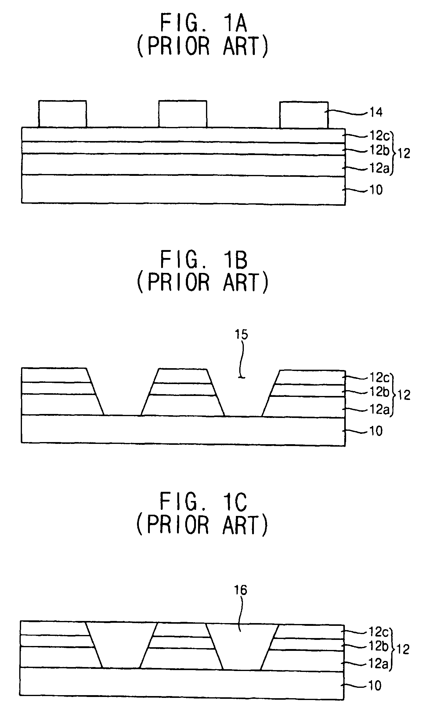
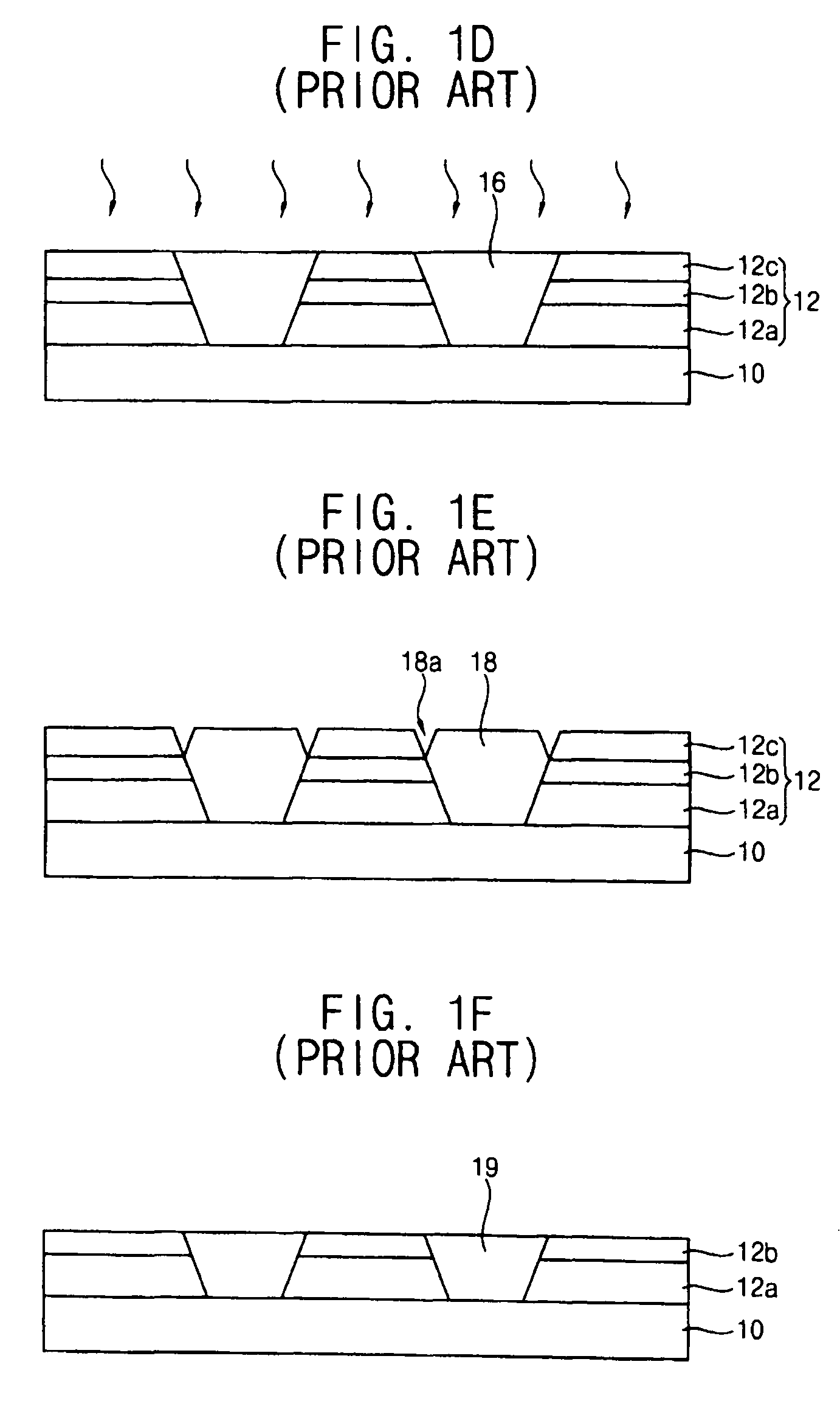
However, under this approach, various SEG process failures have been generated at a boundary surface between the epitaxial layer in the active region and the insulation layer in the field region due to the presence of crystal defects in the SEG process.
Particularly, in the case of a semiconductor device, an active region of a cell area has a relatively small size and has uniform distribution on the substrate, while an active region of a peripheral / core area has a relatively large size and has non-uniform distribution on the substrate.
Therefore, when both the cell area and peripheral / core area of the substrate undergo the same LEG process, the optical energy of a laser sufficient for fully melting the polysilicon layer in the cell area is not sufficient for fully melting the polysilicon layer in the peripheral / core area, and thus the polysilicon layer in the peripheral / core area of the substrate is insufficiently melted by the same LEG process.
That is, the polysilicon layer is not uniformly formed into the single-crystalline silicon layer over the entire peripheral / core area of the substrate due to the local poly grains, which thereby deteriorates the uniformity of the resulting single-crystalline silicon layer and the electrical characteristics of the active region.

Method used


Image

  • Method of manufacturing a semiconductor device including forming a single-crystalline semiconductor material in a first area and forming a second device isolation pattern on a second area
  • Method of manufacturing a semiconductor device including forming a single-crystalline semiconductor material in a first area and forming a second device isolation pattern on a second area
  • Method of manufacturing a semiconductor device including forming a single-crystalline semiconductor material in a first area and forming a second device isolation pattern on a second area

Examples


Embodiment Construction

[0042]This application claims priority under 35 U.S.C. §119 to Korean Patent Application No. 10-2007-0132934, filed on Dec. 18, 2007 in the Korean Intellectual Property Office (KIPO), the content of which is herein incorporated by reference in its entirety.

[0043]Various example embodiments will be described more fully hereinafter with reference to the accompanying drawings, in which some example embodiments are shown. The present invention may, however, be embodied in many different forms and should not be construed as limited to the example embodiments set forth herein. Rather, these example embodiments are provided so that this disclosure will be thorough and complete, and will fully convey the scope of the present invention to those skilled in the art. In the drawings, the sizes and relative sizes of layers and regions may be exaggerated for clarity.

[0044]It will be understood that when an element or layer is referred to as being “on,”“connected to” or “coupled to” another elemen...


PUM


Abstract

In a semiconductor device and a method of manufacturing the same, a first insulation layer is removed from a cell area of a substrate and a first active pattern is formed on the first area by a laser-induced epitaxial growth (LEG) process. Residuals of the first insulation layer are passively formed into a first device isolation pattern on the first area. The first insulation layer is removed from the second area of the substrate and a semiconductor layer is formed on the second area of the substrate by a SEG process. The semiconductor layer on the second area is patterned into a second active pattern including a recessed portion and a second insulation pattern in the recessed portion is formed into a second device isolation pattern on the second area. Accordingly, grain defects in the LEG process and lattice defects in the SEG process are mitigated or eliminated.

Description

BACKGROUND[0001]1. Field[0002]Example embodiments relate to a semiconductor device and a method of manufacturing the same, and more particularly, to a semiconductor device and a method of manufacturing the same in which poly grains are minimized in an active region of a peripheral / core area of a substrate.[0003]2. Description of the Related Art[0004]Generally, conventional manufacturing methods for semiconductor devices usually require device isolation layers for electrically separating unit conductive structures, such as gate structures, in the semiconductor device. One of the most widely known processes for forming a device isolation layer is a field oxidation process. According to the field oxidation formation process, an anti-oxidation pattern is formed on an active region of a substrate on which the unit conductive structures for the semiconductor device and an oxide layer is formed on a field region surrounding and defining the active region in a furnace. The above field oxida...

Claims


Application Information

Patent Timeline
Patent Type & Authority Patents(United States)
IPC IPC(8): H01L21/76H01L21/20H01L21/36
CPCH01L21/76229H01L21/823412H01L21/823481H01L27/0688H01L21/02532H01L21/0262H01L21/02636H01L29/78H01L21/762
Inventor SON, YONG-HOONLEE, JONG-WOOK
Owner SAMSUNG ELECTRONICS CO LTD
Learn More