GMR sensor device having AC power supply

a technology of displacement sensor and power supply, which is applied in the field of displacement sensor, can solve the problems of deviating the actual output voltage waveform obtained, unable to enhance the accuracy of displacement detected from the displacement sensor, and unable to achieve distortion errors, etc., to achieve low cost, high accuracy, and reduce output voltage waveform distortion

Inactive Publication Date: 2010-12-14
HITACHI LTD
View PDF9 Cites 26 Cited by
  • Summary
  • Abstract
  • Description
  • Claims
  • Application Information

AI Technical Summary

Benefits of technology

[0013]It is an object of the present invention to diminish the self-bias effect (anisotropic magnetoresistive effect, AMR effect) generated in the second magnetic layer (also called a detection-side magnetic layer or a free magnetic layer) and thoroughly prevent the occurrence of a distortion error in output voltage of such a displacement sensor using GMR elements as referred to above, by means of a detector circuit of a simple configuration and without impairing the industrial productivity.
[0035]According to the present invention constructed as above, the self-bias effect (also called anisotropic magnetoresistive effect or AMR effect) generated in the second magnetic layer can be diminished fundamentally.

Problems solved by technology

However, such a conventional displacement sensor using GMR elements involves the problem that an actual output voltage waveform obtained is deviated (called a distortion error) from an output voltage waveform obtained from a theoretical value.
This distortion error gives rise to the problem that it is impossible to enhance the accuracy of a detected displacement detected from the displacement sensor.
In an effort to solve the above problem, various countermeasures are proposed in the foregoing patent literatures, but all of them involve demerits and are not decisive solutions.

Method used


Image

  • GMR sensor device having AC power supply
  • GMR sensor device having AC power supply
  • GMR sensor device having AC power supply

Examples


first embodiment

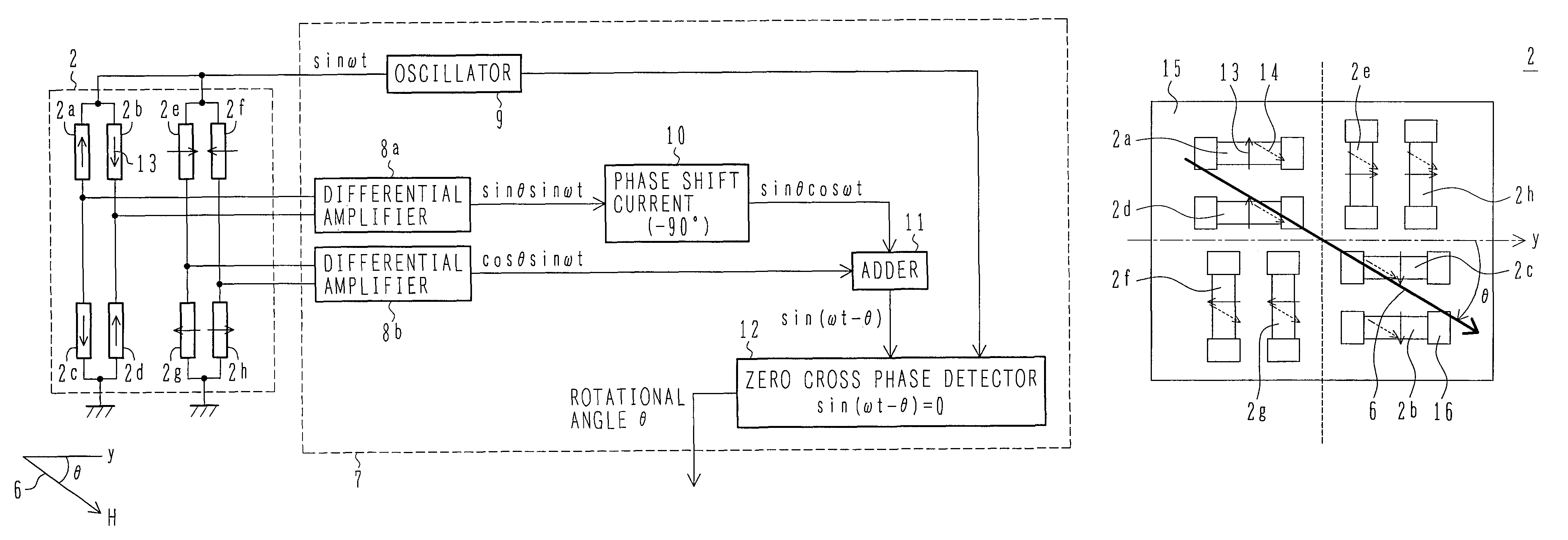
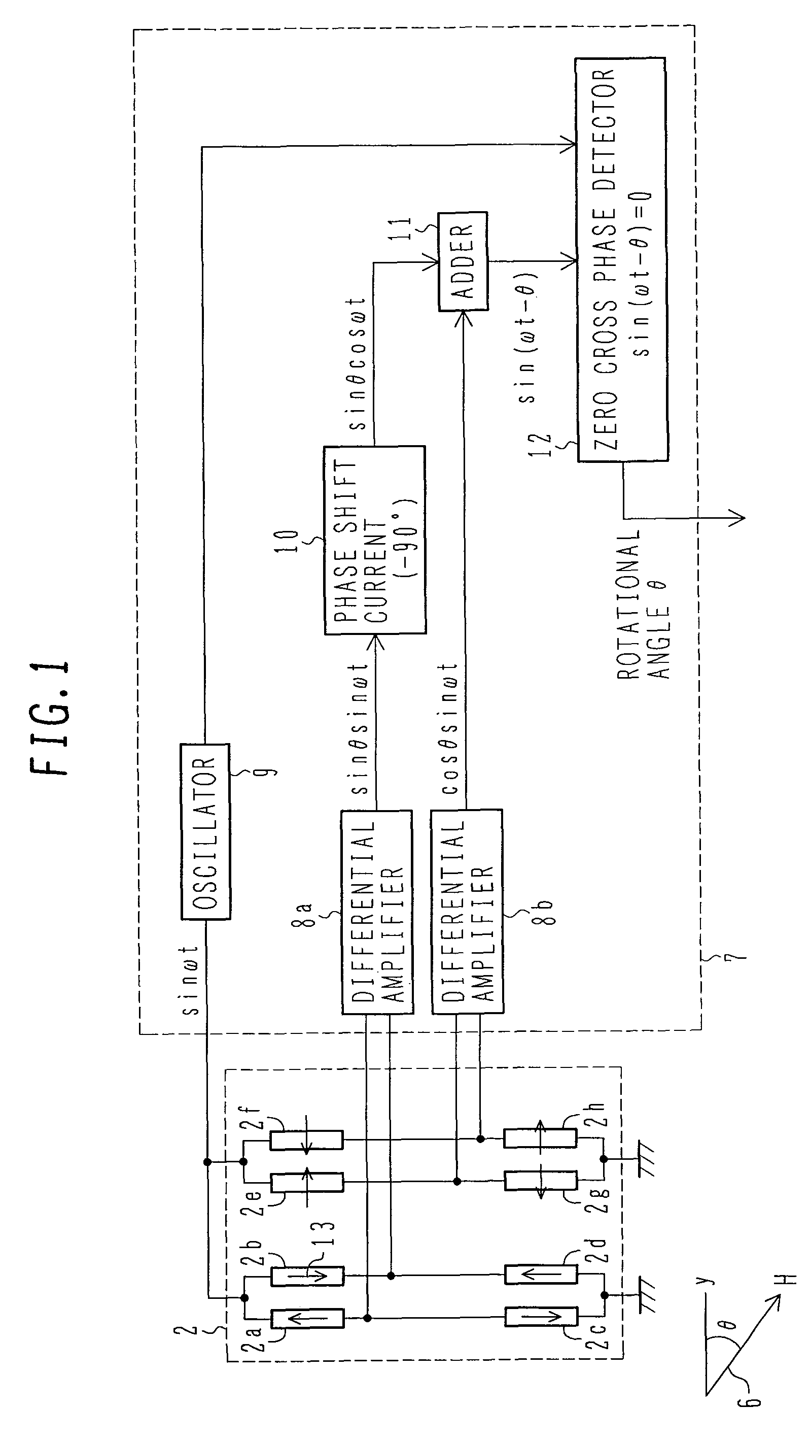
[0086]FIG. 1 is a block diagram of the rotational angle sensor of the present invention.

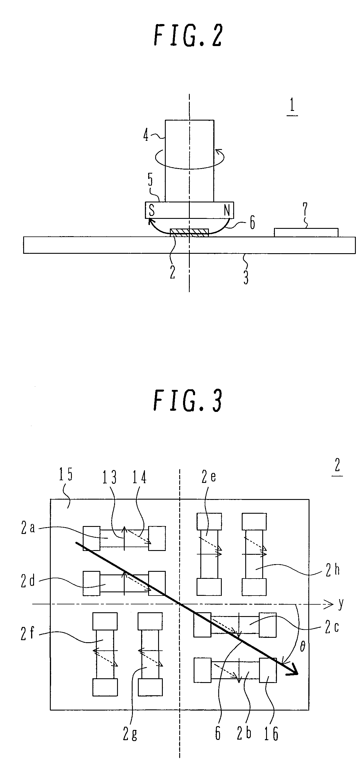
[0087]Each GMR element is wired (not shown) so as to constitute the two Wheatstone bridge circuits shown in FIG. 1, i.e., a first Wheatstone bridge circuit comprising four GMR elements 2a, 2b, 2c and 2d, the GMR elements 2a, 2b, 2c and 2d each having a fixed magnetic layer set in a predetermined magnetization direction parallel or anti-parallel with respect to the reference direction y of the rotational angle, and a second Wheatstone bridge circuit comprising four GMR elements 2e, 2f, 2g and 2h, the GMR elements 2e, 2f, 2g and 2h each having a fixed magnetic layer set in a predetermined ±90° magnetization direction with respect to the reference direction y of the rotational angle.

[0088]As is seen from a sectional structure shown in FIG. 4, each GMR element is constituted by a laminate, the laminate comprising, on a non-magnetic substrate 15, an underlayer 17, an antiferromagnetic layer 18, a fixe...

second embodiment

[0111]FIG. 8 is a block diagram of a rotational angle sensor according to the present invention.

[0112]In this second embodiment, a GMR element sensor section 2 is of the same construction as that in the first embodiment, with a signal processing section 7 in the second embodiment being different in construction from that used in the first embodiment.

[0113]When the AC voltage sin(ωt) is applied from the oscillator circuit 9 to the first and second Wheatstone bridge circuits in the GMR element sensor section 2, an AC-modulated output signal sin θ sin(ωt) is obtained from the first Wheatstone bridge circuit (GMR elements 2a, 2b, 2c and 2d) through the differential amplifier 8a, while an AC-modulated output signal cos θ sin(ωt) is obtained from the second Wheatstone bridge circuit (GMR elements 2e, 2f, 2g and 2h) through the differential amplifier 8b.

[0114]Next, a phase variable φ(0→θ) is generated from a sequential phase generator circuit 27, and cos φ and sin φ are generated from a s...

third embodiment

[0117]FIG. 9 is a block diagram of a rotational angle sensor according to the present invention.

[0118]In this third embodiment, a description will be given about a method for correction in the case where the reference rotational direction y of the rotor section and the magnetization direction 13 of the fixed magnetic layer which is a reference direction of the GMR element sensor section 2 deviate from each other by a variation angle α.

[0119]Ideally, the deviation angle α is required to be zero. However, it does not become zero due to, for example, variations in the manufacturing process and mounting. It is presumed that such variations occur mainly in a magnetizing process for setting the magnetization direction 13 of the fixed magnetic layer in each GMR element, an etching process at the time of forming a resistance pattern of each GMR element, an integral mounting process of each GMR element substrate, and an assembling process of the stator section and the rotor section.

[0120]The...


PUM


Abstract

A highly accurate displacement sensor using GMR elements for detecting displacement of a physical quantity such as angle provides a diminished waveform distortion of output voltage. At least two Wheatstone bridge circuits having a predetermined angular offset are installed, with each bridge circuit including a plurality of GMR elements. Each of the GMR elements has a fixed magnetic layer set to a predetermined magnetization direction. An AC power supply is used, and displacement of a physical quantity, such as a rotational angle, is detected on the basis of AC-modulated outputs from the bridge circuits.

Description

BACKGROUND OF THE INVENTION[0001]1. Field of the Invention[0002]The present invention relates to a displacement sensor using giant magnetoresistive (hereinafter referred to as GMR) elements to detect a displacement of a physical quantity such as, for example, a displacement of an angle, a gradient, or a stroke. In particular, the present invention is concerned with such a displacement sensor having means for correcting a waveform distortion of an output voltage. The present invention is also concerned with a semiconductor device used for such a sensor.[0003]2. Description of the Related Art[0004]Such a displacement sensor using GMR elements and a semiconductor device used for the sensor are known from, for example, JP-A-2003-121197, JP-A-2005-24287 and JP-A-2006-170837.[0005]The GMR elements are each provided with a first magnetic layer (also called a reference magnetic layer, a fixed magnetic layer, or a pin magnetic layer) whose magnetization direction is set in a specific directi...

Claims


Application Information

Patent Timeline
Patent Type & Authority Patents(United States)
IPC IPC(8): G01B7/30H01L43/06G01R33/09
CPCG01D5/145
Inventor YAMADA, MASAMICHIKANEKAWA, NOBUYASUNAKABAYASHI, KENJI
Owner HITACHI LTD
Why Eureka
Try Eureka