Method and needle webbing loom in order to weave a ribbon

a technology of weaving loom and ribbon, which is applied in the field of weaving a ribbon, can solve the problems of inability to produce variations of any kind, impaired stability of the ribbon to be produced,

Active Publication Date: 2010-12-28
TEXTILMA AG
View PDF33 Cites 15 Cited by
  • Summary
  • Abstract
  • Description
  • Claims
  • Application Information

AI Technical Summary

Benefits of technology

[0004]The object of the invention is to improve the method for weaving a ribbon on a needle ribbon machine having two simultaneously and contradirectionally operating weft needles.
[0005]Since only that weft which is presented to one of the two weft needles is inserted, any desired weft sequence is possible. Not just two weft threads may be introduced simultaneously into the shed, as is afforded in the prior art, but, in particular, the weft threads may be inserted alternately from ribbon sides to ribbon sides, so that, in the event of each shed change, only one weft thread loop is inserted. Furthermore, it is possible, moreover, to present weft threads even of changing color and quality to the weft needles. This not only affords a mechanically improved quality of the ribbon produced, but the pattern possibility is also increased.

Problems solved by technology

The disadvantage, then, is that always two weft thread loops have to be inserted into a common shed, so that, in the event of a shed change, two weft thread loops, that is to say four weft thread portions, have to be tied in simultaneously.
The stability of the ribbon to be produced is impaired as a result.
There are also no variations of any kind possible, since closed weft needles having guide loops on which a weft thread is always arranged are used.

Method used


Image

  • Method and needle webbing loom in order to weave a ribbon
  • Method and needle webbing loom in order to weave a ribbon
  • Method and needle webbing loom in order to weave a ribbon

Examples


Embodiment Construction

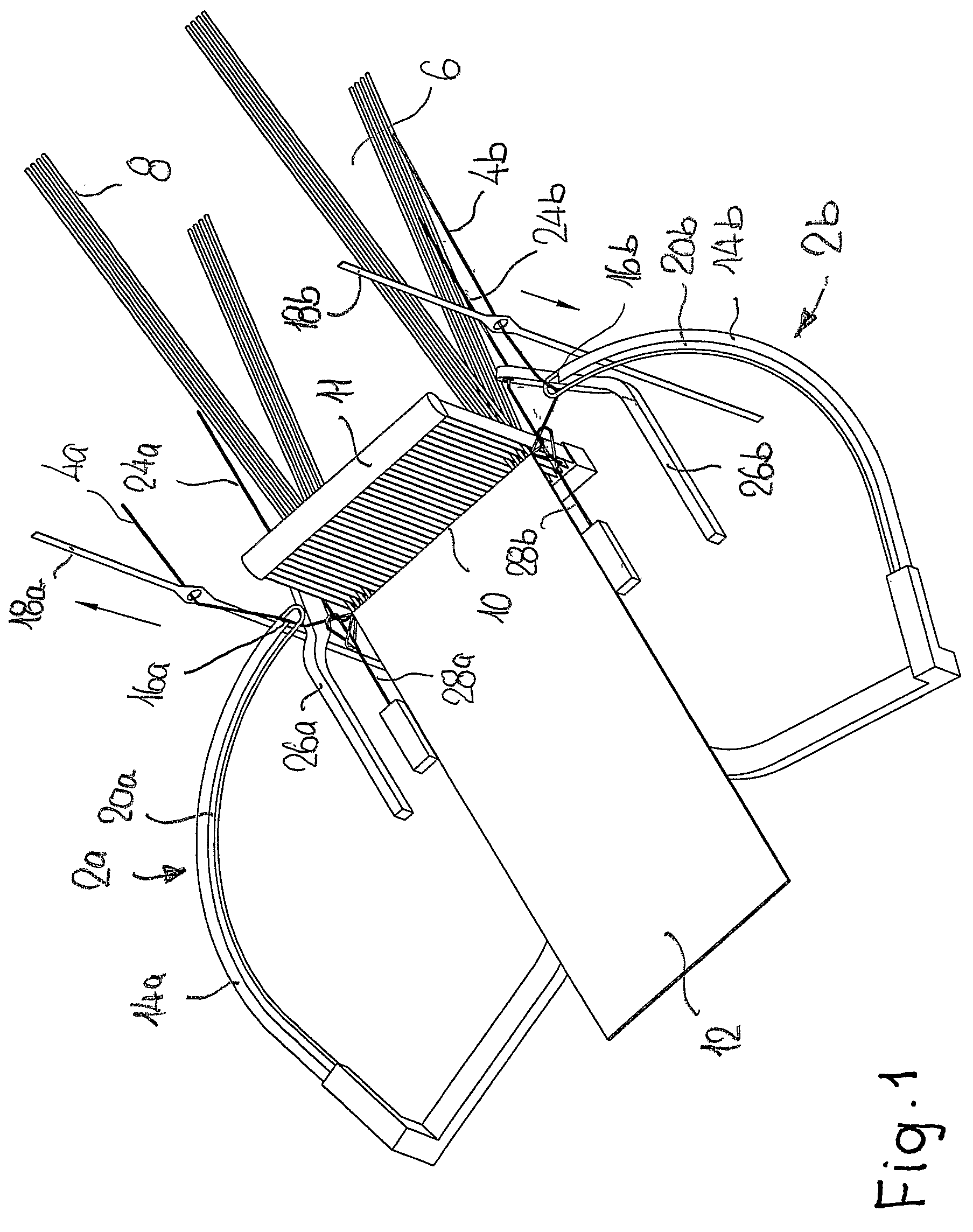
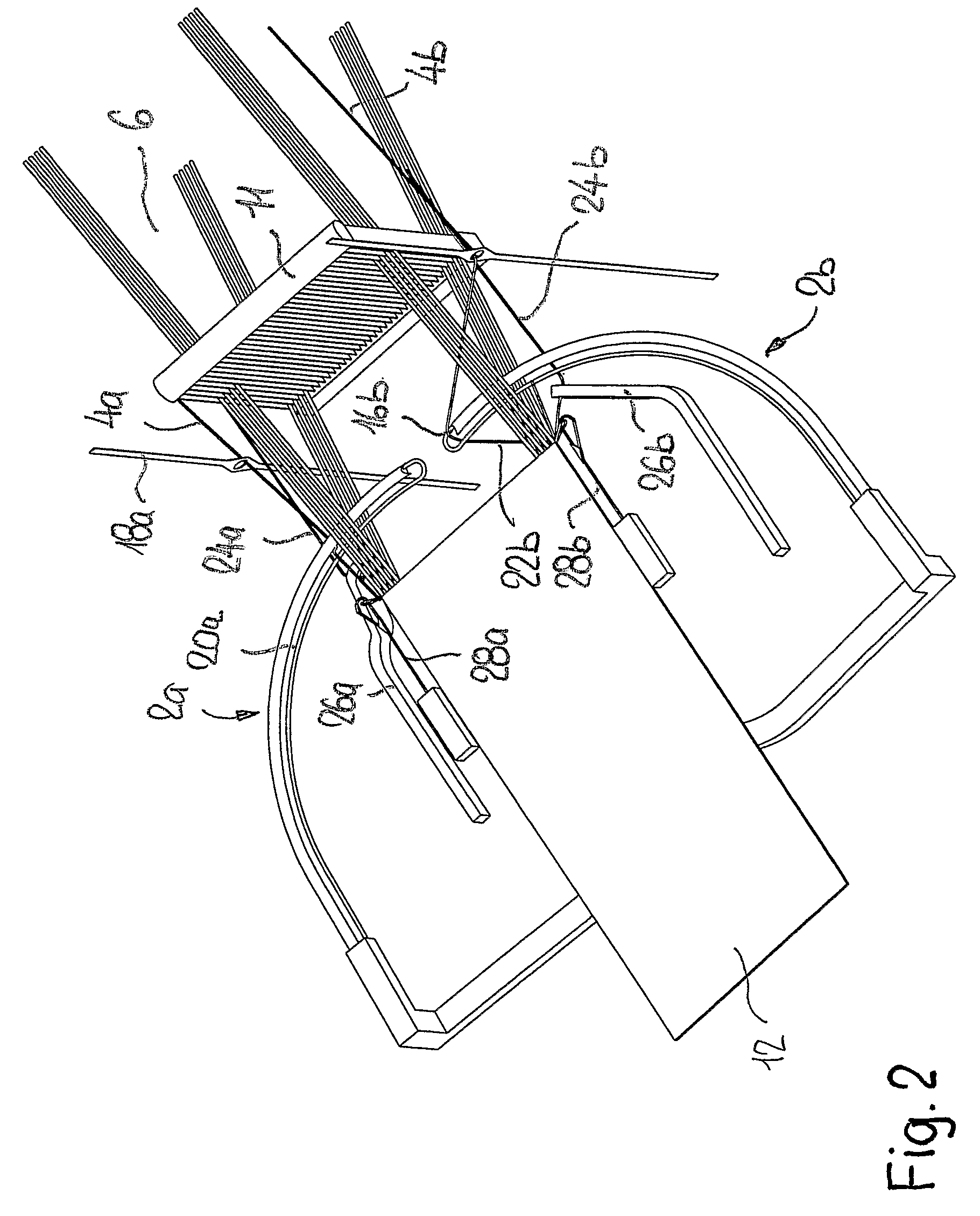
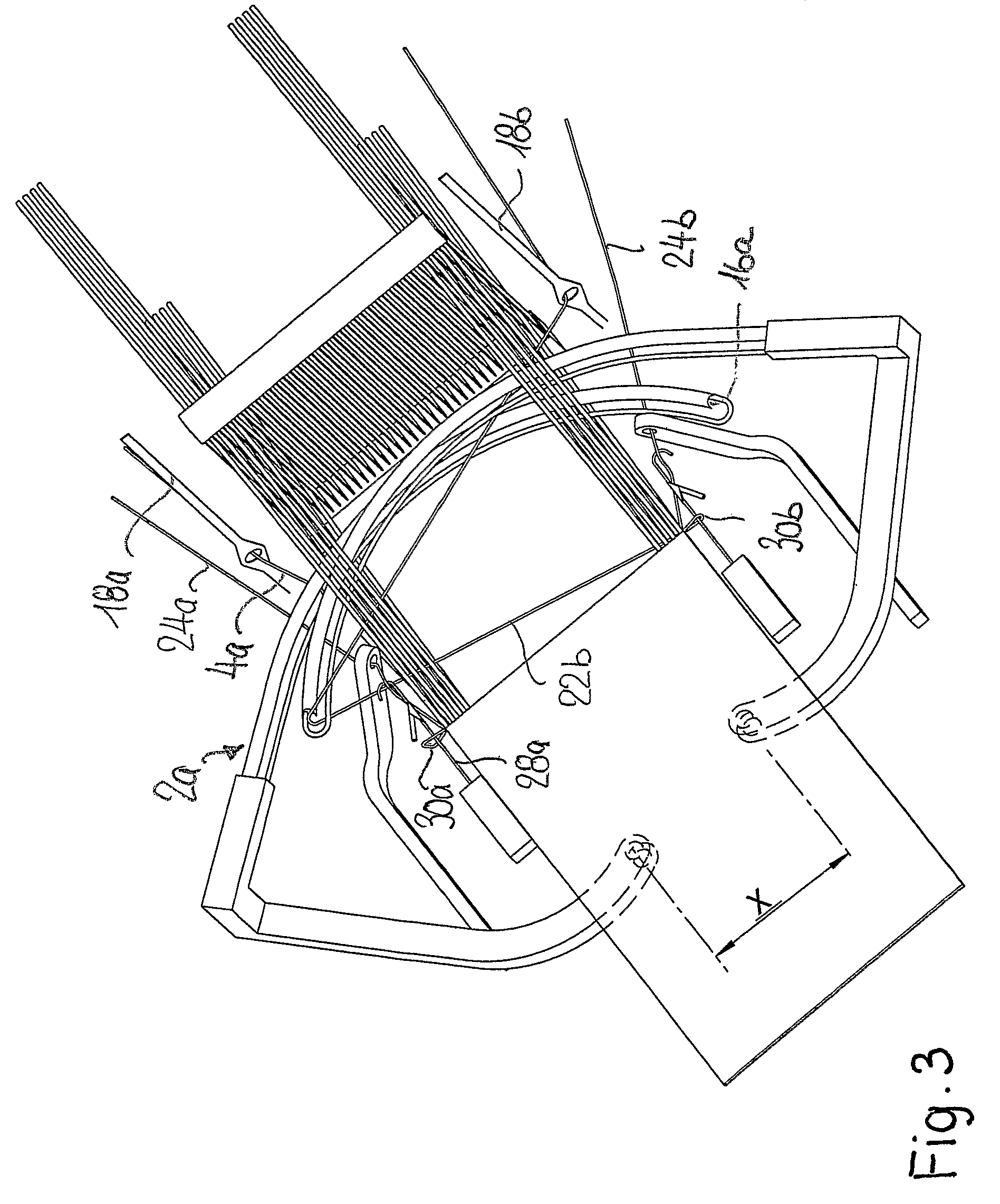
[0017]FIGS. 1 to 4 show the weaving region of a needle ribbon weaving machine with two contradirectionally driven weft needles 2a, 2b which insert weft threads 4a, 4b into a shed 6. In the shed 6 formed from warp threads 8, the weft threads are beaten up at the beating-up edge 10 by means of a reed 9, thus giving rise to the ribbon 12.

[0018]The weft needles 2a, 2b are in each case open needles, i.e. they have at the front end of a needle shank 14a, 14b a fork 16a, 16b, into which the respective weft thread 4a, 4b is introduced by means of a thread lifter 18a, 18b movable up and down. The weft needles 2a, 2b contain in each case guide slots 20a, 20b which run along the needle shank 14a, 14b and which reach beyond the forks 16a, 16b. The guide slots 20a, 20b serve for guiding the weft thread 4a, 4b when the weft thread is not inserted into the shed 6, and for making it easier to introduce into the fork 16a, 16b with the aid of the respective thread lifter 18a, 18b. The web thread loop...


PUM


Abstract

A needle webbing machine which comprises two weft needles (2a, 2b) which work simultaneously and in opposite directions on both ribbon sides, in addition to knitting needles (28a, 28b) which are arranged on both ribbon sides. A yarn lifter (18a, 18b) which works individually and which is used to advance a weft thread (4a, 4b) to a weft needle (2a, 2b), which is open, is provided on each side of the ribbon in order to improve the production thereof.

Description

[0001]This application claims priority of PCT application PCT / CH2006 / 000489 having a priority date of Oct. 6, 2005, the disclosure of which is incorporated herein by reference.TECHNICAL FIELD[0002]The invention relates to a method for weaving a ribbon on a needle ribbon weaving machine and to a needle ribbon weaving machine.BACKGROUND OF THE INVENTION[0003]A method and a needle ribbon weaving machine for weaving a ribbon of the type initially mentioned are known from DE 40 09 455A. The method described there for producing a ribbon on a needle ribbon weaving machine takes place by means of two closed weft needles operating contradirectionally, the ribbon being woven by both weft needles as a result of insertion into a common shed. The heads of the contradirectionally inserted weft thread loops are secured on each ribbon side by means of wales which are formed in each case from an auxiliary thread and which are located at the two edges of the ribbon. The disadvantage, then, is that al...

Claims


Application Information

Patent Timeline
Patent Type & Authority Patents(United States)
IPC IPC(8): D03D47/44D03D35/00D03D47/08D03D41/00
CPCD03D47/06D03D47/38
Inventor SPEICH, FRANCISCOPROBST, ANTON
Owner TEXTILMA AG
Why Eureka
Try Eureka