Coil component

a coil and component technology, applied in the field of coil components, can solve the problems of prone to breakage, fragile against bending, brittle core body, etc., and achieve the effect of improving the inductance value of the coil component, preventing breakage, and improving the overall magnetic path magnetic permeability

Active Publication Date: 2010-12-28
SUMIDA CORP
View PDF6 Cites 35 Cited by
  • Summary
  • Abstract
  • Description
  • Claims
  • Application Information

AI Technical Summary

Benefits of technology

[0007]An object of the present invention, which has been made to solve the above problems, is to provide a coil component which can be deformed itself by following the flex, which is caused as a time elapses, of a flexible printed board on which it is mounted, is highly resistant against drop shock, and has a high inductance value.
[0008]To achieve the present invention, the inventors have paid attention to that the magnetic powder contained in the resin in the conventional flexible inductor described in US2006 / 0214759A1 uses ordinary metal magnetic powder and soft magnetic ferrite powder, that is, a compound magnetic sheet in the inductor is made by simply dispersing isotropic magnetic powder to the resin. The inventors have completed the present invention based on a technical idea that the mechanical merit of a flexible inductor can be obtained and further the inductance value of the inductor can be improved by increasing the magnetic permeability of a compound magnetic sheet according to the direction in which a magnetic flux radiated by the inductor passes.

Problems solved by technology

In the inductor, a core body is very brittle and is fragile against bending and shock impact.
For this reason, when the inductors are used in power supply circuits and the like for a mobile device, a problem arises in that it is liable to be broken by deflection, deformation due to elapse, or dropping impact of a substrate.

Method used


Image

  • Coil component
  • Coil component
  • Coil component

Examples


examples

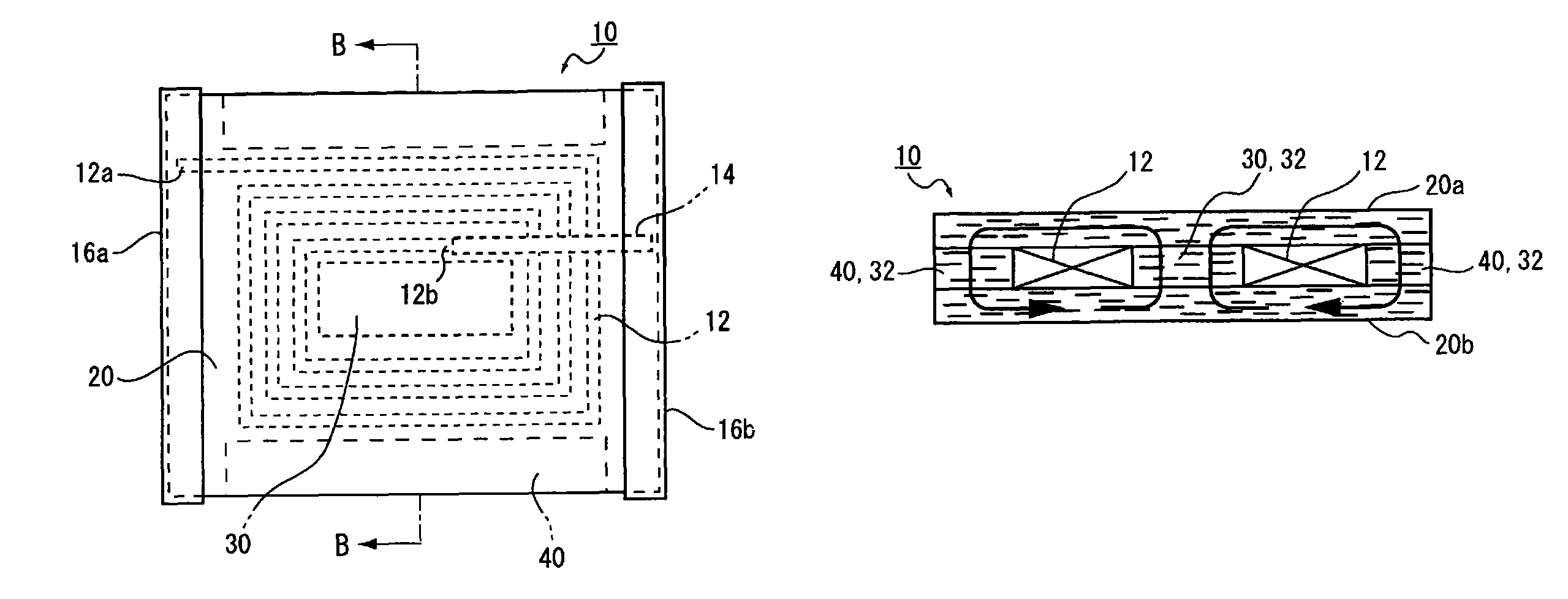
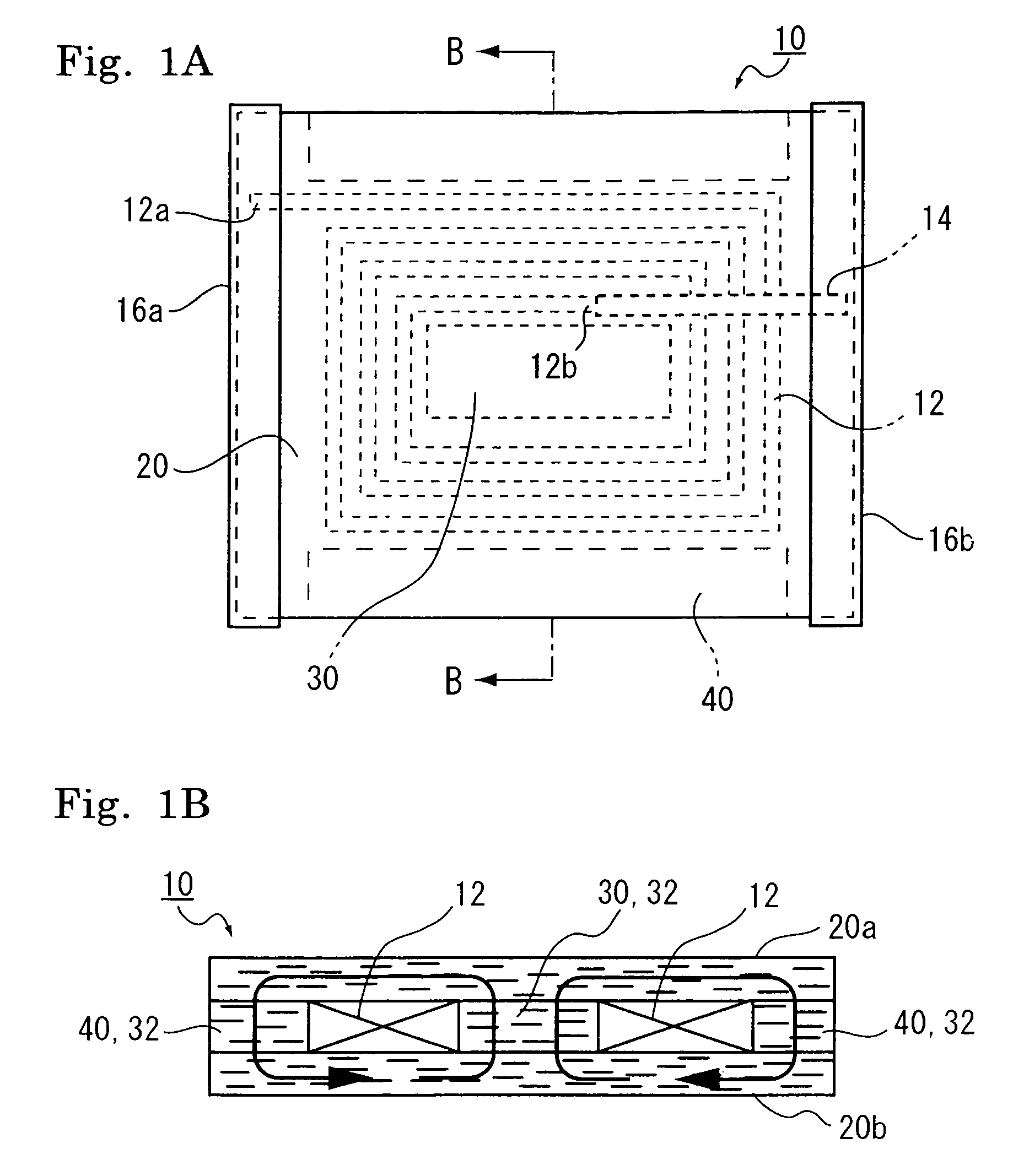
[0107]Inductance values [μH] and superimpose direct-current characteristics [A] were simulated as to each inductor 10 of the first embodiment as shown in the sectional view of FIG. 1B, the second embodiment as shown in the sectional view of FIG. 4A, the third embodiment as shown in the sectional view of FIG. 4B, the fourth embodiment as shown in the sectional view of FIG. 4C, and the seventh embodiment as shown in the sectional view of FIG. 5C. Further, as a comparative example, the inductance value and superimpose direct-current characteristics were simulated likewise as to an inductor 11 arranged such that isotropic metal powder was dispersed in compound magnetic sheets 21 layered on both the upper and lower surfaces of an air core coil 12 and further a central core 30 and a periphery 40 were respectively filled with the isotropic compound magnetic material 35 as shown in the sectional view of FIG. 7.

[0108]With regard to the anisotropic compound magnetic material 20 and the anisot...


PUM

PropertyMeasurementUnit
thicknessaaaaaaaaaa
glass transition temperatureaaaaaaaaaa
widthaaaaaaaaaa

Abstract

A coil component is provided, and the coil component for an inductor is deformable dependent on flex of a flexible printed board due to elapse of time when mounted thereon, and has high resistance against dropping impact and has an inductance value. The coil component includes an anisotropic compound magnetic sheet which is layered on at least any one or both of the upper surface and the lower surface of an air core coil formed spirally in a plane and which is composed of flat or needle-shaped soft magnetic metal powder, which has a major axis and a minor axis and is dispersed in a resin material, the major axis of which corresponds to an in-plane direction of the air core coil.

Description

BACKGROUND OF THE INVENTION[0001]1. Field of the Invention[0002]The present invention relates to a coil component used in a power supply circuit and the like for a mobile device such as a mobile phone.[0003]2. Description of the Related Art[0004]As a conventional coil, an inductor laminated ferrite sintered bodies which have respectively a built-in conductor, has been widely used as disclosed in Japanese Patent Application Laid-Open (JP-A) No. 2005-268369. In the inductor, a core body is very brittle and is fragile against bending and shock impact. For this reason, when the inductors are used in power supply circuits and the like for a mobile device, a problem arises in that it is liable to be broken by deflection, deformation due to elapse, or dropping impact of a substrate.[0005]To solve the problem, there is proposed a flexible inductor configured such that a compound magnetic material (compound magnetic sheet) obtained by mixing a magnetic powder with a resin is layered on a fil...

Claims


Application Information

Patent Timeline
Patent Type & Authority Patents(United States)
IPC IPC(8): H01F27/02
CPCH01F17/0006H01F17/04H01F2017/0066H01F2017/048
Inventor KAWARAI, MITSUGU
Owner SUMIDA CORP
Why Eureka
Try Eureka