
Laser drivers for closed path optical cables

a technology of optical cables and laser drivers, applied in multiplex communication, semiconductor lasers, instruments, etc., can solve the problems of limited bandwidth and distance of digital video and/or audio cables, limited current cables and solutions, and other problems, to achieve the effect of reducing and increasing the cost of repeaters

Inactive Publication Date: 2010-12-28
II VI DELAWARE INC
View PDF163 Cites 61 Cited by
  • Summary
  • Abstract
  • Description
  • Claims
  • Application Information

AI Technical Summary

Problems solved by technology

These current cables and solutions, as well as others, are limited in many ways in their capabilities to carry digital video and / or audio signals.
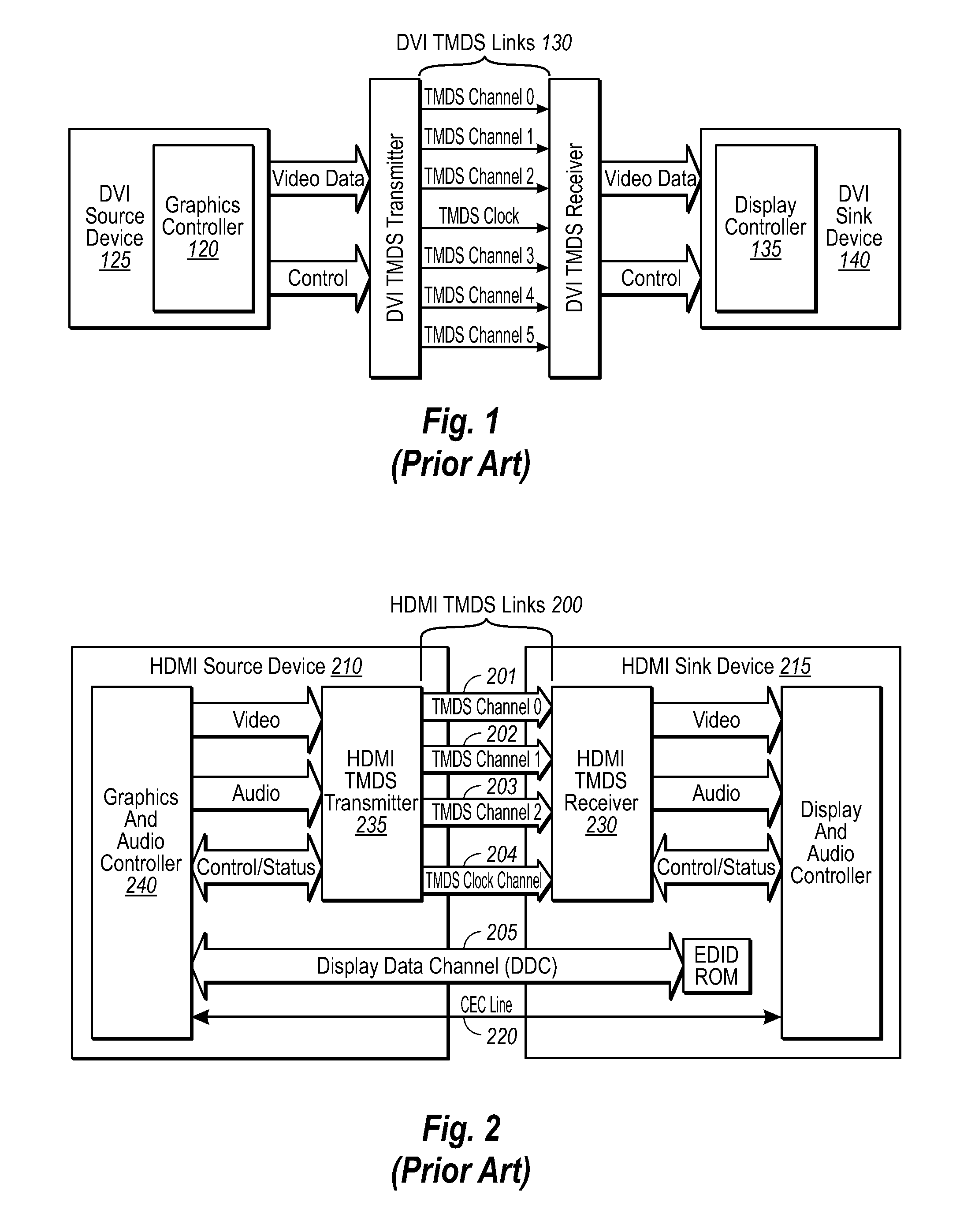
For example, these digital video and / or audio cables are limited in bandwidth and distance in which they can carry TMDS signals.
However, a repeater can be quite expensive, add additional hardware and circuitry, require additional cables for the extension, and even still be relatively limited in distances to which the repeater can transmit digital video and / or audio signals and bandwidth of the cables.
Therefore, repeaters have not provided a desired solution to many of the problems currently experienced with these cables, but rather have tried to mitigate the limitations of such cables.

Method used


Image

  • Laser drivers for closed path optical cables
  • Laser drivers for closed path optical cables
  • Laser drivers for closed path optical cables

Examples


Embodiment Construction

[0051]The principles of the present invention are described with reference to the attached drawings, which illustrate the structure and operation of example embodiments used to implement the present invention. Using the diagrams and description in this manner to present the invention should not be construed as limiting its scope. Additional features and advantages of the invention will in part be obvious from the description, including the claims, or may be learned by the practice of the invention.

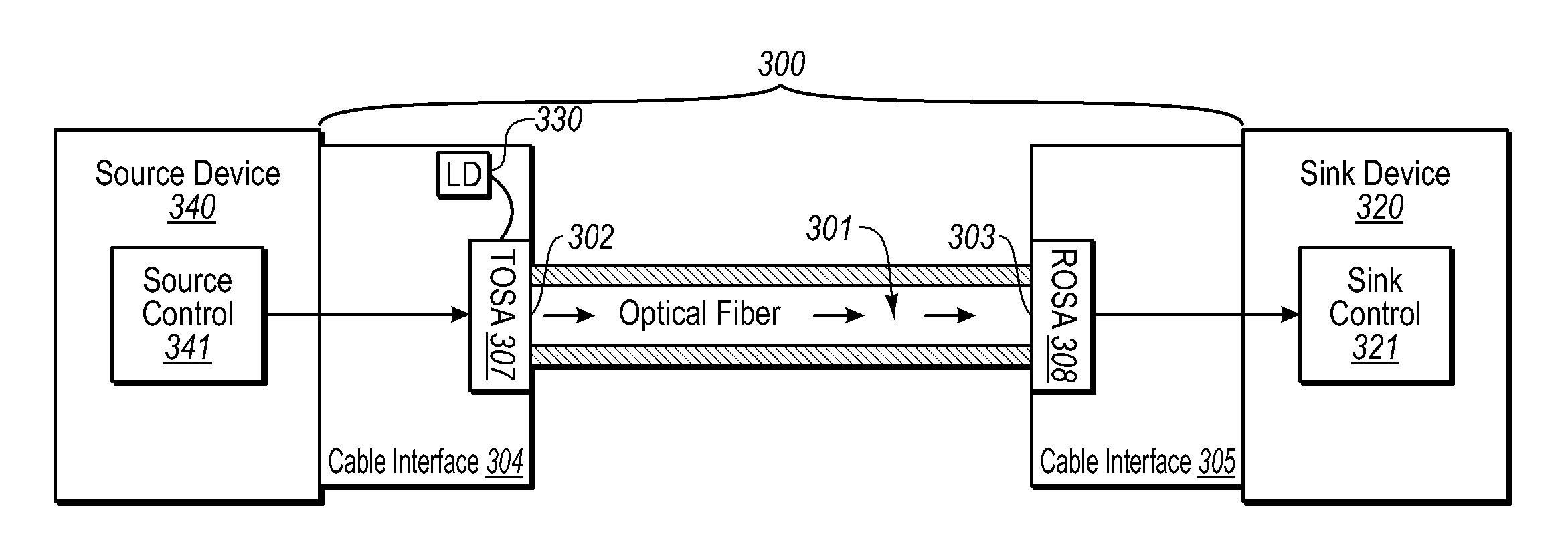
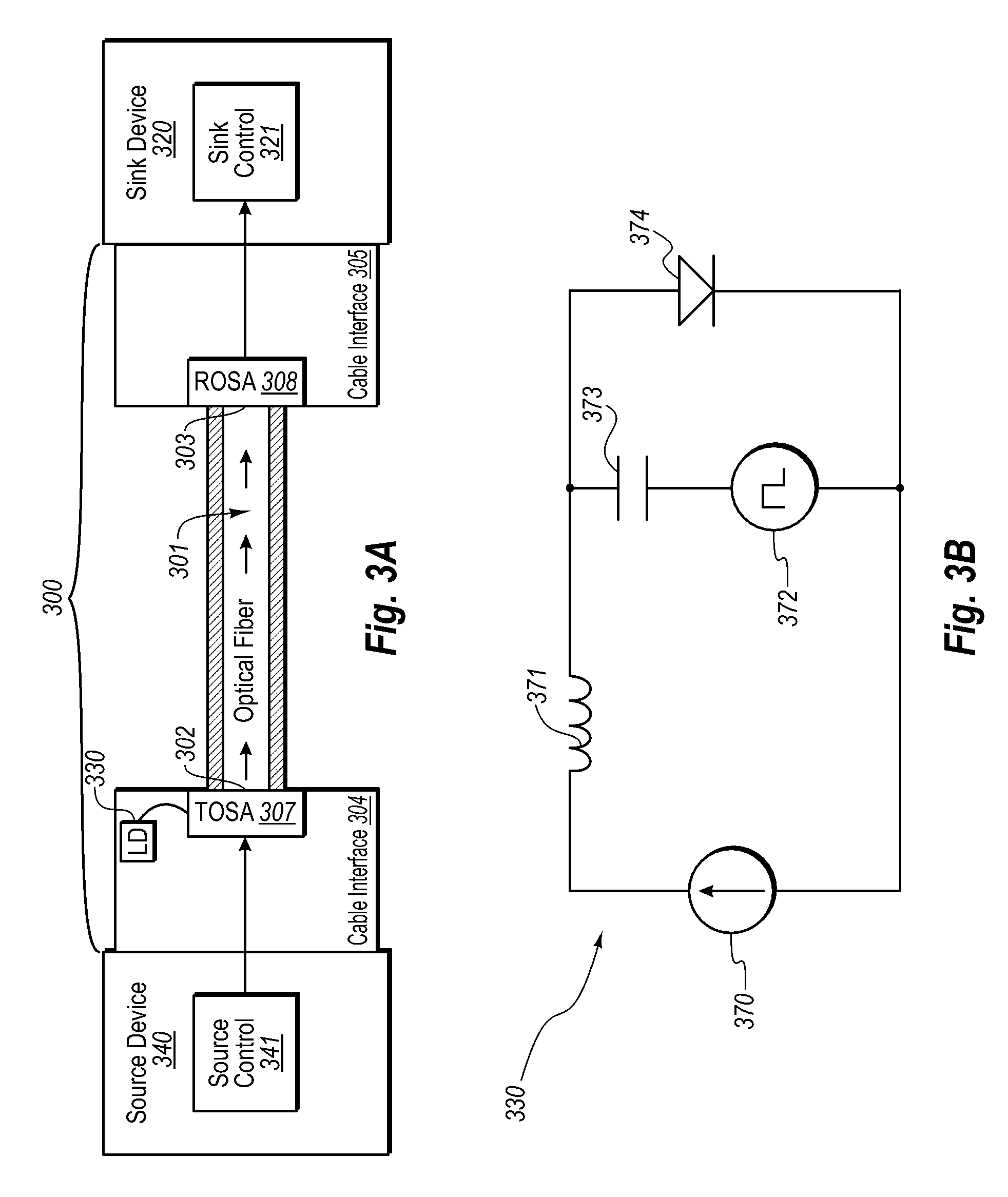
[0052]Digital optical cables discussed herein can include a laser (e.g. a VCSEL) for transmitting an optical signal over an optical fiber. The digital optical cables can be closed path in that all of the optical components are contained within the optical cables. As a result, the laser of the digital optical cables discussed below may not need to conform to at least some of the industry standards or other operating constraints required in the past. Thus, one aspect of several embodiments r...


PUM


Abstract

Simplified laser drivers for closed path digital optical cables and digital optical cables including the simplified laser drivers. The laser driver can include less transistors than conventional laser drivers for optical communication cables. The laser can include a bias source and modulation source. The bias source can have a single constant current bias point for all laser diodes. The modulation current source can have a single temperature coefficient for all laser diodes. The laser driver can exclude, for example, any one of or combination of temperature compensation of the modulation or bias current sources, external programming of the modulation or bias current sources, power control based on output of the laser diode, and / or control based on feedback received from a monitor device or other sensor within the cables.

Description

CROSS-REFERENCE TO RELATED APPLICATIONS[0001]This application claims the benefit of U.S. Provisional Patent Application No. 60 / 717,352 filed Sep. 15, 2005, the contents of which are hereby incorporated herein by reference. This application is related to U.S. patent application Ser. No. 11 / 198,619 filed on Aug. 5, 2005, entitled “Optical Cables for Consumer Electronics”, which claims the benefit of U.S. Provisional Application No. 60 / 614,199 filed on Sep. 29, 2004 entitled “Optical DVI Cables”, the contents of both applications are hereby incorporated herein by reference. This application is related to U.S. patent application Ser. No. 10 / 316,355 entitled “OPTICAL TRANSCEIVER” filed Dec. 11, 2002, which is a CIP of U.S. patent application Ser. No. 10 / 163,057, filed Jun. 4, 2002, entitled “OPTICAL TRANSCEIVER”, the contents of both applications are incorporated by reference herein. This application is related to U.S. patent application Ser. No. 10 / 308,308, entitled “BIDIRECTIONAL OPTIC...

Claims


Application Information

Patent Timeline
IPC IPC(8): H04B10/00
CPCG02B6/4201G02B6/4246H04B10/801G09G5/006H01S5/0262H01S5/0425H01S5/18313H01S5/3095H04J14/08G09G2370/12G09G2370/18H01S5/04257H01S5/005H01S5/02H01S5/02212
Inventor TATUM, JIMMY A.GUENTER, JAMES K.
Owner II VI DELAWARE INC
Learn More