
Press forming die set and method

a technology of press forming and die set, which is applied in the field of press forming technique, can solve the problems of increasing the amount of cut material, poor yield, and the space to the inside of the fixing beads, and achieves the effects of reducing the friction of the second bead, simple structure, and reducing the size of the blank

Inactive Publication Date: 2011-01-04
HONDA MOTOR CO LTD
View PDF3 Cites 6 Cited by
  • Summary
  • Abstract
  • Description
  • Claims
  • Application Information

AI Technical Summary

Benefits of technology

[0011]In this arrangement, the first bead as a fixing bead is disposed on the inside, and the second bead as a movable bead is disposed on the outside. Since the fixing bead is disposed on the inside, the amount of cut material is reduced, and the yield rate is satisfactory when the edges are cut after forming.
[0014]In this method, since forming at the initial stage of forming is performed while the blank is restrained by an intermediate restraining force, wrinkles can be prevented from occurring. Since forming at the intermediate stage of forming is performed while the blank is restrained by a small restraining force, cracks can be prevented from occurring. Since forming at the final stage of forming is performed while the blank is restrained by a large restraining force, the shape of the formed article can be satisfactorily regulated.
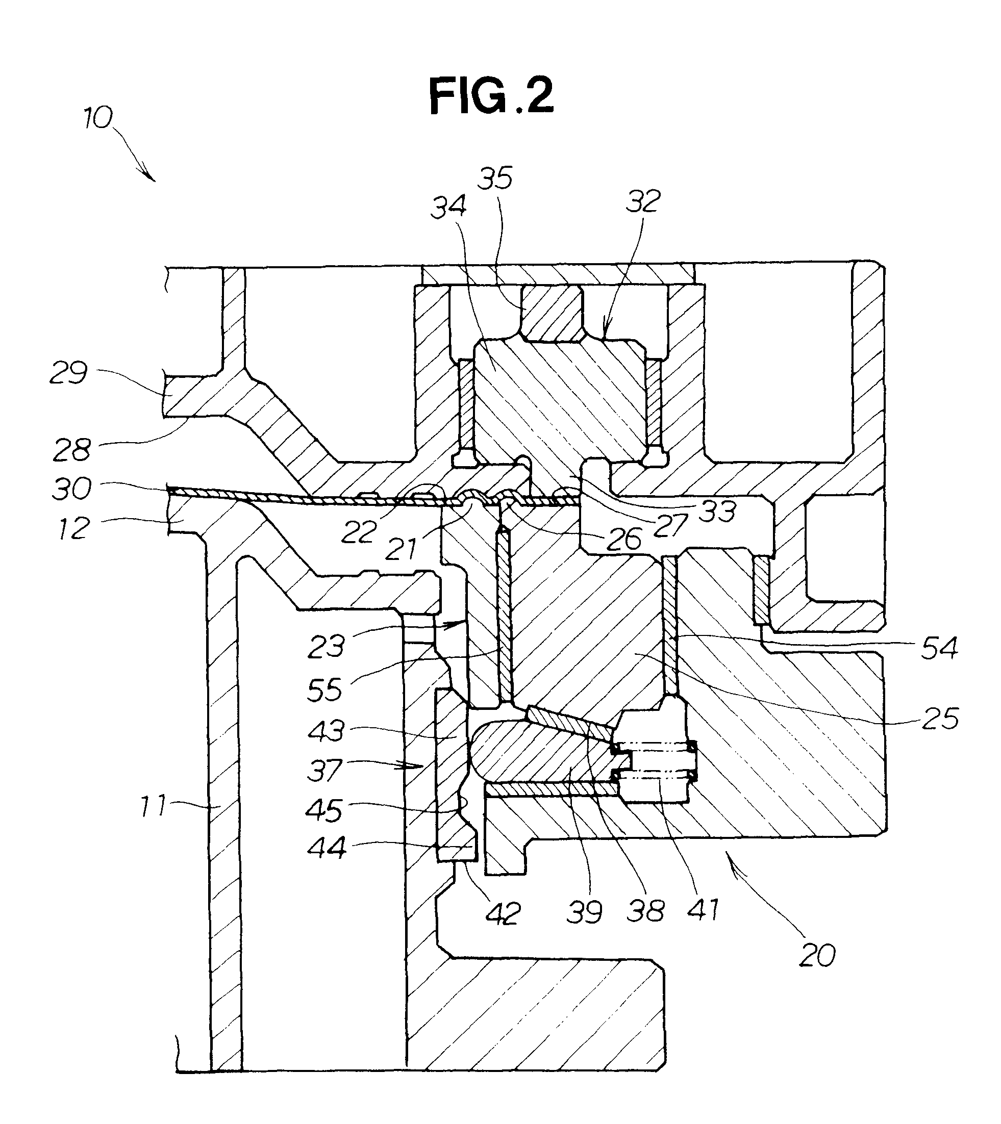
[0016]In the this arrangement, since the second bead moves together with the second holder surface, the restraining force of the second blank holder is shared between the second bead and the second holder surface. As a result, there is no risk of the restraining force being concentrated at the second bead, and the amount of friction on the second bead can be significantly reduced.
[0017]Since the second bead is formed by a portion of the second blank holder, there is no risk of the second bead solely changing position with respect to other members. As a result, the restraining force provided by the second bead is stabilized.
[0018]Furthermore, the blank holder is divided into a first blank holder and a second blank holder, and there is therefore no need for the second bead to be housed in the blank holder. As a result, the press forming die can be endowed with a simple structure.
[0019]Preferably, the second bead is provided in a position nearer the convex part than the second holder surface, at an edge of the second blank holder. Since the second bead is disposed adjacent to the convex part, the blank can be reduced in size, and material cost can be reduced.

Problems solved by technology

When the fixing beads 103 are provided to the outside, the amount of cut material increases, and the yield is poor when the edges of the formed article are cut off after forming.
However, the space to the inside of the fixing beads 103 is limited, and the movement mechanism is therefore subject to space limitation, and unavoidably has a complex structure.
A complex movement mechanism is not preferred, because the cost of the press apparatus increases.

Method used


Image

  • Press forming die set and method
  • Press forming die set and method
  • Press forming die set and method

Examples


Embodiment Construction

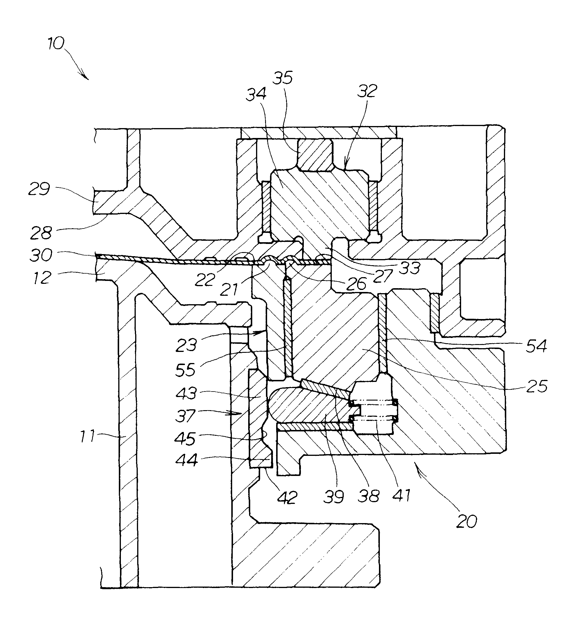
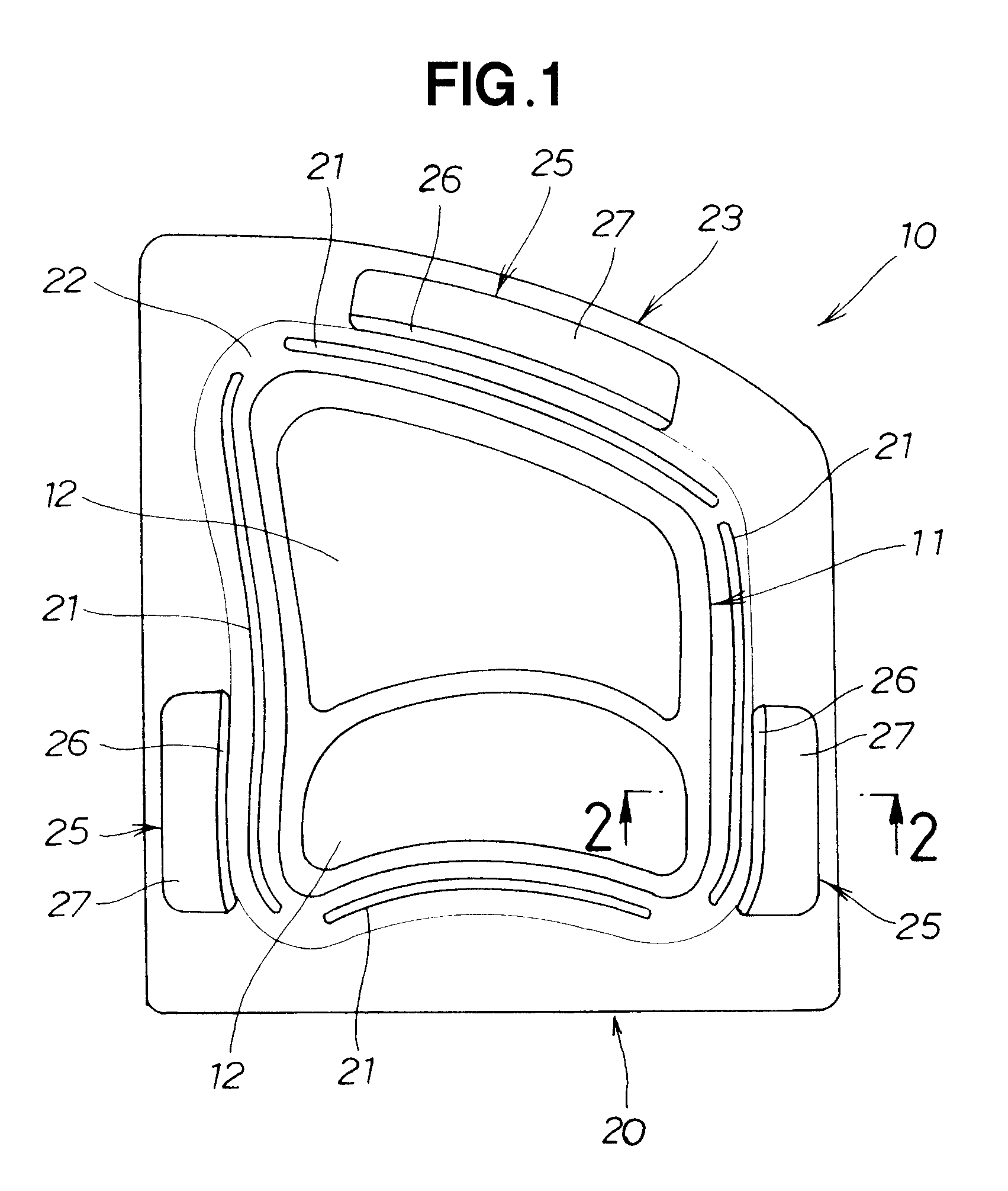
[0031]As shown in FIG. 1, a punch 11 of a press forming die set 10 is provided with convex parts 12, 12. A blank holder 20 is also provided so as to surround the punch 11.

[0032]The blank holder 20 is composed of a first blank holder 23 having first beads 21, 21, 21, 21 that function as fixing beads, and a first holder surface 22 that is a mouth-shaped flat surface; and second blank holders 25, 25, 25 that are housed within the first blank holder 23 so as to be able to move in the front and back directions in the drawing.

[0033]The second blank holders 25 have a second bead 26 that functions as a movable bead, and a second holder surface 27 that is an I-shaped flat surface. The second bead 26 is disposed closer to the convex part 12 than the second holder surface 27, i.e., further inward.

[0034]Specifically, the second bead 26 is provided to the edge of the second blank holder 25 so as to be closer to the convex part 12 than the second holder surface 27.

[0035]Since the blank holder 20 ...


PUM

PropertyMeasurementUnit
restraining forceaaaaaaaaaa
forceaaaaaaaaaa
constant forceaaaaaaaaaa

Abstract

A die set for press-forming a blank of thin metallic sheet. The die set has a punch and a blank holder. The blank holder has a first bead for restraining an edge of the blank with a constant force. The first bead is disposed further to an inside than a second bead for restraining the edge of the blank with a force that varies during pressing of the blank.

Description

CROSS REFERENCE TO RELATED APPLICATIONS[0001]This application claims priorities of Japanese patent applications 2007-025539 filed Feb. 5, 2007 and 2007-028362 filed Feb. 7, 2007.FIELD OF THE INVENTION[0002]The present invention relates to a press forming technique for draw-forming a thin metal sheet.BACKGROUND OF THE INVENTION[0003]A press-formed article can be obtained by placing a blank in a die provided with a concave part and drawing the convex part of a punch into the concave part. At this time, when the edges of the blank are held down by a blank holder, a neat formed article can be obtained that is free of wrinkles. However, rather than simply holding down the edges of the blank, it is preferable to adjust the restraining force in accordance with the progress of the press, i.e., the degree of progress of the draw process.[0004]A press apparatus capable of adjusting the restraining force has been proposed in the past, e.g., in Japanese Patent Application Laying-Open Publicatio...

Claims


Application Information

Patent Timeline
Patent Type & Authority Patents(United States)
IPC IPC(8): B21D22/00
CPCB21D22/22B21D25/04
Inventor NAKAMURA, TSUYOSHIKITANO, YASUHIKOISHIHARA, YOSHIMITSUMAEDA, SHINGO
Owner HONDA MOTOR CO LTD
Learn More