Non-lethal projectile

a projectile and non-lethal technology, applied in the field of projectiles, can solve the problems of non-lethal weapons being required for controlling crowds in violent demonstrations, the possibility of inflicting injury on an alleged suspect, and the tragic injury or death of an innocent bystander, so as to reduce the maximum force, prolong the duration of the impulse, and reduce the effect of for

Active Publication Date: 2011-01-04
FACTA GLOBAL INC
View PDF16 Cites 38 Cited by
  • Summary
  • Abstract
  • Description
  • Claims
  • Application Information

AI Technical Summary

Benefits of technology

[0012]According to another aspect of the present invention, a projectile is provided for use in a non-lethal weapon system. The projectile includes a first body with a longitudinal axis. The projectile having kinetic energy is launched substantially along the longitudinal axis in the direction of a target. Upon impact of the projectile with the target an elastic mechanism absorbs elastically a first portion of the kinetic energy. The elastic mechanism preferably reduces the maximum force that the projectile exerts on the target during the impact. The elastic mechanism initially during the impact absorbs elastically a second portion of the kinetic energy which is stored elastically as stored energy within the elastic mechanism. After the initial impact with the target the elastic mechanism releases the stored energy to the target thus extending the duration of the impulse but at a lower force. Alternatively, a locking mechanism stores the first portion of the kinetic energy within the elastic mechanism; whereby the remaining kinetic energy of the impact is reduced to a non-lethal level of the target. The projectile preferably includes a deformable head attached to the first body. The deformable head is formed from a viscoelastic material which manifests both the elastic mechanism (with the elastic mechanical properties of the viscoelastic material) and further manifests the locking mechanism with the viscous properties of the viscoelastic material. The elastic mechanism preferably includes a spring which is deformed upon the impact, and stores elastically the first portion of the kinetic energy. This stored energy can be optionally delivered later to the target by releasing the locking mechanism. Alternatively or in addition, the projectile preferably includes a second body with the same longitudinal axis and a hollow. A portion of the first body fits marginally within the hollow. The elastic mechanism includes an elastic deformation of the first body and / or second body while the first body is forced into the hollow during the impact. The first body is preferably externally ridged with first ridges and the hollow is internally ridged with matching second ridges. While the first body is forced into the hollow during the impact, the locking mechanism includes locking the first ridges on the second ridges. The first ridges and second ridges are preferably shaped to prevent release of the elastic mechanism. Alternatively, the locking mechanism is performed using a frictional mechanism which dissipates another portion of the kinetic energy as energy of kinetic friction between the first body and the second body.

Problems solved by technology

However, the use of conventional weapons by the law enforcement personnel is limited by the possibility of inflicting injury to an alleged suspect, since the courts and not law enforcement personnel have the responsibility for determining guilt and sentencing a criminal.
Even worse the use of conventional weapons by law enforcement personnel may lead to a tragic injury or death of an innocent bystander.
Furthermore, non-lethal weapons are required for controlling crowds in violent demonstrations.
Rubber and plastic bullets are typically too energetic to be used at distances less than about 25 meters and become ineffective at distances greater than 50 meters.
Conventional rubber and plastic bullets have caused a significant number of unwanted injuries.

Method used


Image

  • Non-lethal projectile
  • Non-lethal projectile
  • Non-lethal projectile

Examples


Embodiment Construction

[0025]Reference will now be made in detail to embodiments of the present invention, examples of which are illustrated in the accompanying drawings, wherein like reference numerals refer to the like elements throughout. The embodiments are described below to explain the present invention by referring to the figures.

[0026]Before explaining embodiments of the invention in detail, it is to be understood that the invention is not limited in its application to the details of design and the arrangement of the components set forth in the following description or illustrated in the drawings. The invention is capable of other embodiments or of being practiced or carried out in various ways. Also, it is to be understood that the phraseology and terminology employed herein is for the purpose of description and should not be regarded as limiting.

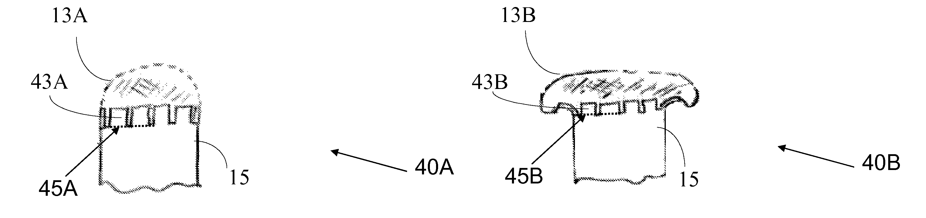
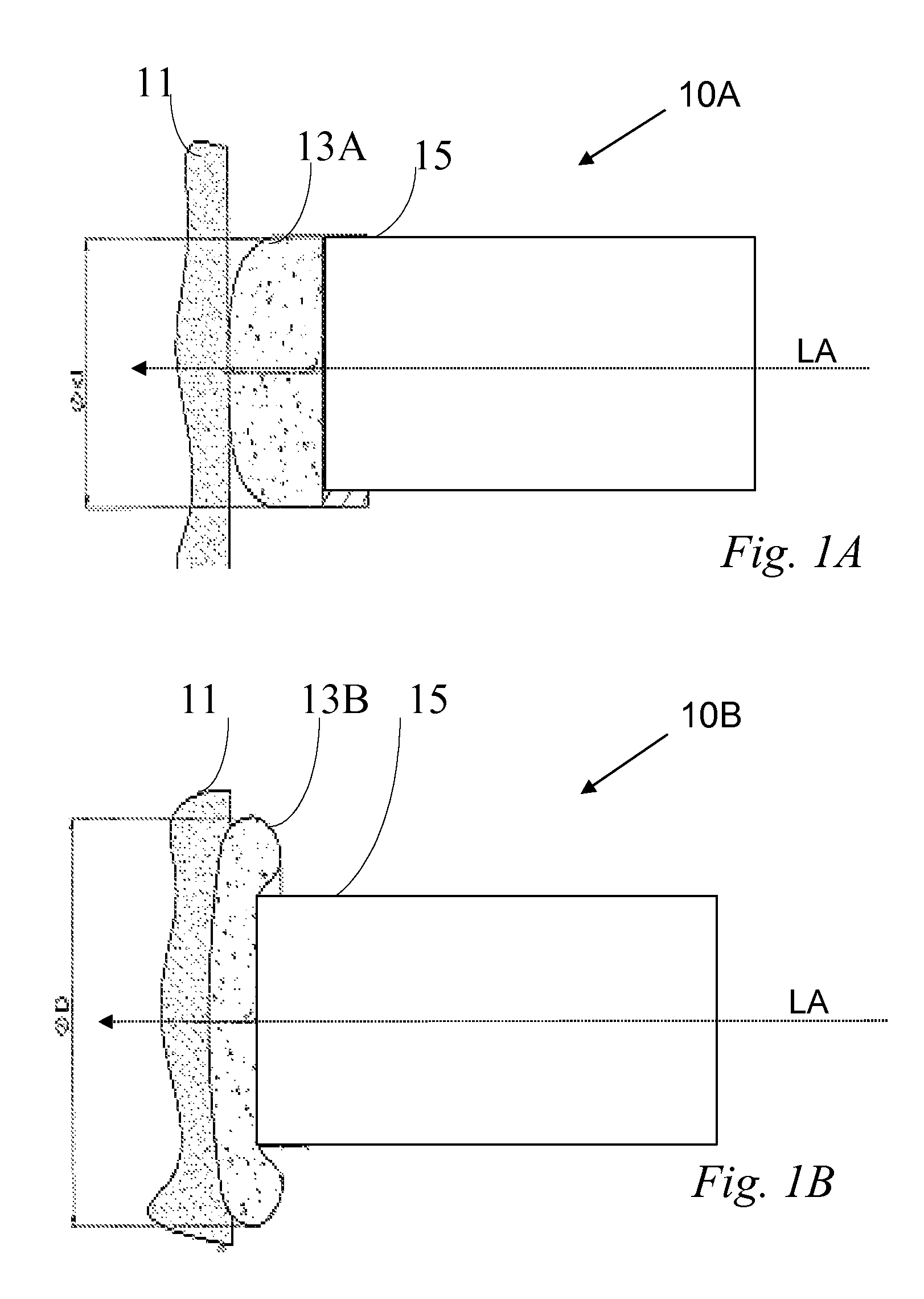
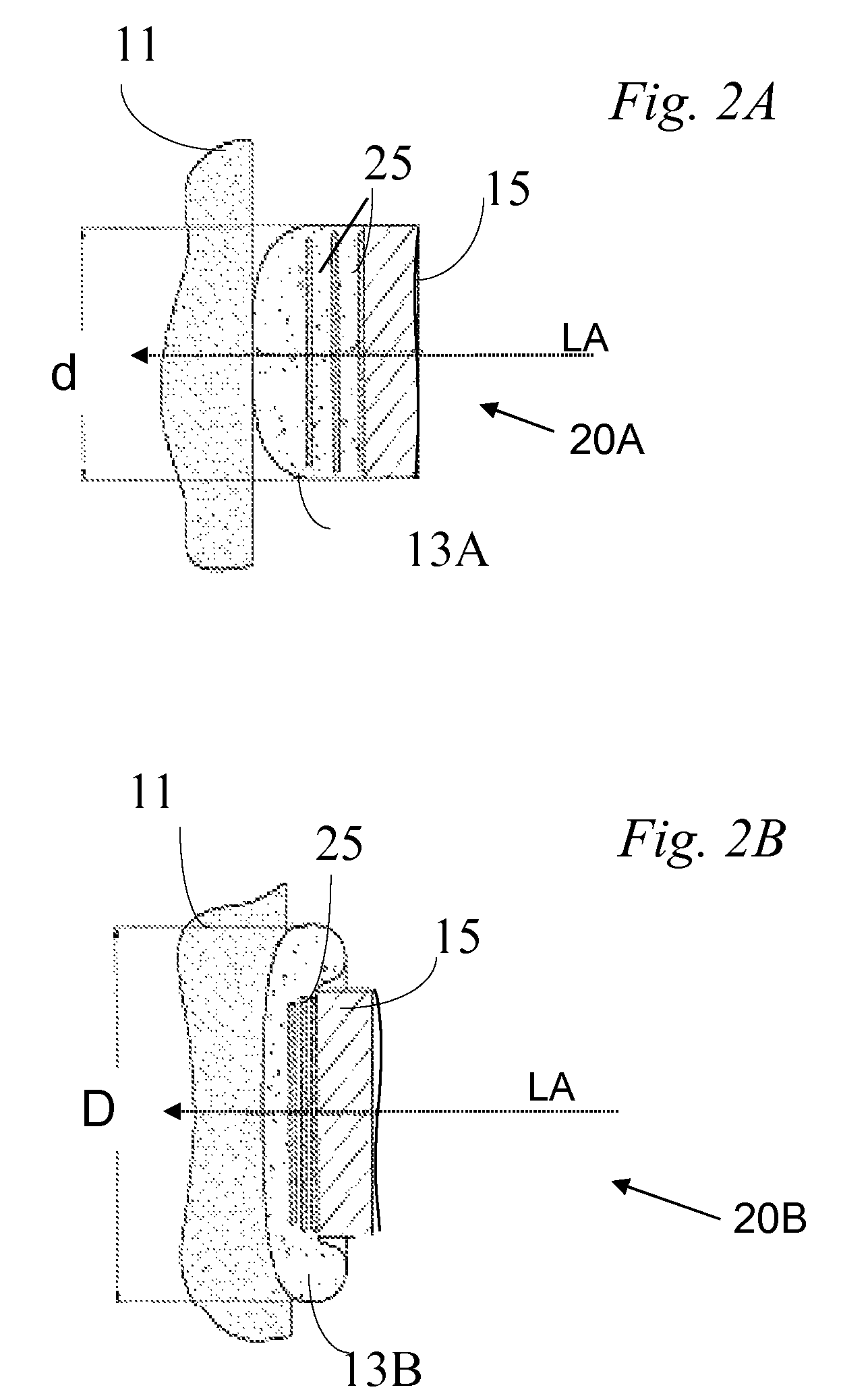
[0027]By way of introduction, embodiments of the present invention are applicable to projectiles fired at high speed, for example by standard weaponry, ...


PUM


Abstract

A projectile is provided for use in a non-lethal weapon system. The projectile having kinetic energy is launched substantially along the longitudinal axis in the direction of a target. Upon impact of the projectile with the target an elastic mechanism absorbs elastically a first portion of the kinetic energy. A locking mechanism stores the first portion of the kinetic energy within the elastic mechanism; whereby the remaining kinetic energy of the impact is reduced to a non-lethal level of the target. The projectile preferably includes a deformable head attached to the first body. The deformable head is formed from a viscoelastic material which manifests both the elastic mechanism (with the elastic mechanical properties of the viscoelastic material) and further manifests the locking mechanism with the viscous properties of the viscoelastic material.

Description

CROSS REFERENCE TO RELATED APPLICATION[0001]The present application claims the benefit of U.S. provisional application 60 / 909,461 filed on Apr. 1, 2007, by the present Applicants, the disclosure of which is included herein by reference.FIELD AND BACKGROUND[0002]The present invention relates to a projectile used for incapacitation of a human being or animal target and more specifically mechanisms for absorbing kinetic energy of the non-lethal projectile.[0003]Conventional weapons are used by law enforcement personnel to deter and subdue criminals. However, the use of conventional weapons by the law enforcement personnel is limited by the possibility of inflicting injury to an alleged suspect, since the courts and not law enforcement personnel have the responsibility for determining guilt and sentencing a criminal. Even worse the use of conventional weapons by law enforcement personnel may lead to a tragic injury or death of an innocent bystander. Furthermore, non-lethal weapons are r...

Claims


Application Information

Patent Timeline
Patent Type & Authority Patents(United States)
IPC IPC(8): F42B12/02
CPCF42B12/34F42B30/02F42B12/74F42B12/36F42B8/12F42B12/02F42B12/72
Inventor DANON, HAIMSHALEV, ILAN
Owner FACTA GLOBAL INC
Why Eureka
Try Eureka