Travelator and method for controlling the operation of a travelator

a technology of traveler and control device, which is applied in the direction of escalators, hoisting equipment, conveyor parts, etc., can solve the problems of affecting the minimum tightening force needed by the traction element, the element and the drive wheel and the diverting wheel wear quickly, and the service life of the traction element becomes maximally long, and the damage of the equipment due to the effect of too small tightening for

Inactive Publication Date: 2011-01-04
KONE CORP
View PDF14 Cites 15 Cited by
  • Summary
  • Abstract
  • Description
  • Claims
  • Application Information

AI Technical Summary

Benefits of technology

[0026]One advantage of the invention is that it presents an easy way for automatic adjustment of the tightening force of the traction element according to a predicted, i.e. known before the starting of the travelator, or drive-time drive status such that the traction element is not continuously subjected to a large tightening force, but only according to need, in which case the service life of the traction element becomes maximally long.
[0027]A further advantage is that damage of the equipment due to tightening force that is too small is effectively prevented.
[0028]In one embodiment of the travelator the identification means are arranged to identify a change in the drive status during the operation of the conveyor, and the adjustment means are arranged to adjust the tightening force of the tightening device to different force levels based on the identified change in the drive status.
[0029]In one embodiment of the travelator the drive direction of the conveyor can be changed. The identification means are arranged to identify the drive status, which is the setting of the forthcoming drive direction before the starting of the conveyor in the drive direction defined by the setting.
[0030]In one embodiment of the travelator the identification means are arranged to identify the drive status, which is the load exerted on the conveyor.
[0031]In one embodiment of the travelator the identification means are arranged to identify a change in the load exerted on the conveyor.

Problems solved by technology

One problem is the minimum tightening force needed by the traction element, which is substantially greater in the reverse drive direction than in the forward drive direction.
Furthermore the load exerted on the conveyor affects the tightening force needed.
One problem with this is that the traction element and the drive wheel and the diverting wheel then wear quickly, in which case their service life and servicing interval become short.

Method used


Image

  • Travelator and method for controlling the operation of a travelator
  • Travelator and method for controlling the operation of a travelator
  • Travelator and method for controlling the operation of a travelator

Examples


Embodiment Construction

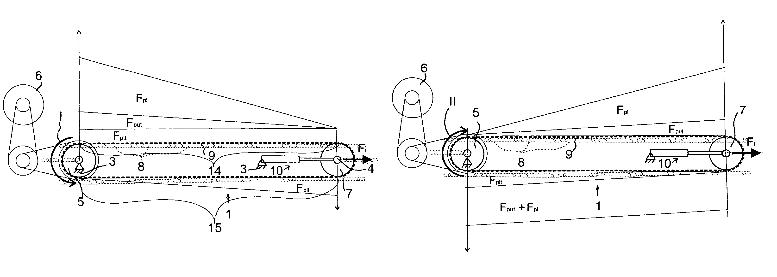
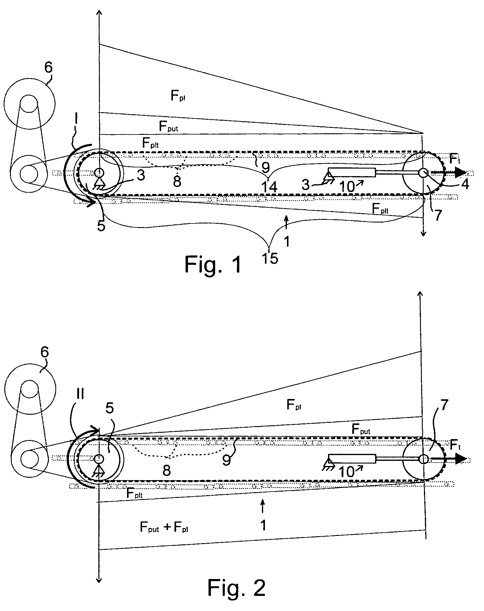
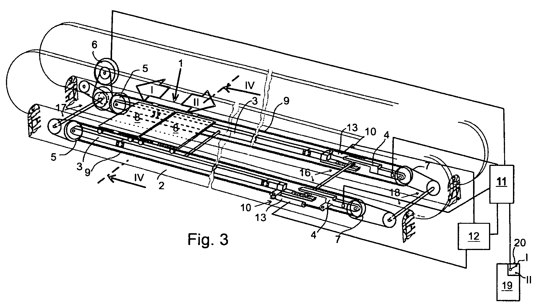
[0053]FIGS. 3 and 4 show a travelator, which is of low construction, installed on a fixed base, such as on the floor or other support, which means that a recess for the machineries of the travelator does not need to be made in the fixed base, such as the floor. In the following description of the embodiment the invention is described in connection with a horizontal travelator, but it is obvious that the corresponding principles of the invention can also be applied to inclined moving ramps.

[0054]The travelator comprises a conveyor 1, which can be e.g. a pallet conveyor, in which is a plurality of consecutive transport surfaces 8, of which only two are presented diagrammatically in FIG. 3 for the sake of clarity.

[0055]The conveyor 1 comprises a frame formed of two halves, both of which are referred to in this description simply as the frame 2. The frame 2 comprises a first frame half 3, which is essentially fixed in its stationary position, and a second frame half 4, which is controll...


PUM


Abstract

Travelator, the conveyor of which comprises a frame, which comprises a stationary first frame part and a second frame part that moves in relation to it. The drive wheel is mounted on a bearing allowing rotation onto the first frame part. The power unit rotates the drive wheel. The diverting wheel is mounted on a bearing allowing free rotation onto the second frame part. The transport surfaces are connected to a traction element which is formed as an endless loop, and which is led to pass over the drive wheel and the diverting wheel. The tightening device is arranged to act between the first frame part and the second frame part to move the diverting wheel linearly away from the drive wheel in order to exert tightening force on the traction element. The travelator comprises identification means for identifying the drive status of the conveyor, and adjustment means for adjusting the tightening force of the tightening device to different force levels based on the drive status identified. In the method the drive status of the conveyor is identified, and the tightening force of the endless traction element of the conveyor of the travelator is adjusted on the basis of the drive status identified.

Description

[0001]This application is a Continuation of copending PCT International Application No. PCT / FI2006 / 00283 filed on Aug. 25, 2006, which designated the United States, and on which priority is claimed under 35 U.S.C. §120. This application also claims priority under 35 U.S.C. §119(a) on Patent Application No(s). 20050903 filed in Finland on Sep. 9, 2005. The entire contents of each of the above documents is hereby incorporated by reference.FIELD OF THE INVENTION[0002]The present invention relates to a travelator as defined in the preamble of claim 1. In addition, the present invention relates to a method as defined in the preamble of claim 13.BACKGROUND OF THE INVENTION[0003]A prior-art travelator diagrammatically presented in FIGS. 1 and 2. This type of travelator comprises a conveyor, which conveys passengers from one end of the travelator to the other. The conveyor comprises a frame. The frame is divided into two parts. The first frame part 3 is essentially fixed in its position, an...

Claims


Application Information

Patent Timeline
Patent Type & Authority Patents(United States)
IPC IPC(8): B65G15/00B65G23/16B65G23/24B65G43/00B66BB66B23/18B66B23/22B66B25/00
CPCB66B23/18B66B25/00
Inventor AULANKO, ESKOMUSTALAHTI, JORMAOSSENDORF, MARC
Owner KONE CORP
Why Eureka
Try Eureka