Sheet post-processing apparatus and sheet post-processing method

a post-processing apparatus and sheet technology, applied in the field of sheet post-processing, can solve the problems of increasing the speed of discharging sheets, and achieve the effect of suppressing the speed fluctuation

Active Publication Date: 2011-01-04
KK TOSHIBA +1
View PDF9 Cites 11 Cited by
  • Summary
  • Abstract
  • Description
  • Claims
  • Application Information

AI Technical Summary

Benefits of technology

[0008]It is an object of the present invention to provide a sheet post-processing apparatus and a sheet post-processing method for maintaining, even when a small number of sheets are conveyed from a processing tray to a stacking tray, discharge speed of a trailing end of the sheets during sheet discharge at predetermined speed and suppressing fluctuation in speed to thereby stack the sheets on the stacking tray in an aligned state.
[0022]In the sheet post-processing apparatus and the sheet post-processing method, the bundle claw is attached to the sheet conveyor belt that conveys sheets from the processing tray to the stacking tray, the bundle claw includes the concave portion having the bottom surface for regulating a position of a trailing end of the sheets, and, in the bottom surface, the surface on the lower side that comes into contact with the sheet conveyor belt is formed deeper than the surface on the upper side to form the step portion between the surface on the lower side and the surface on the upper side. Therefore, when a small number of sheets are discharged from the processing tray to the stacking tray, a trailing end of the sheets is located on the lower surface side of the concave surface of the bundle claw, where the trailing end of the sheets should be originally located, and does not move to the upper surface side of the concave surface of the bundle claw. As a result, fluctuation in discharge speed of the sheets is reduced and it is possible to perform stable paper discharge.

Problems solved by technology

As a result, speed of discharging the sheets falls increasing.

Method used


Image

  • Sheet post-processing apparatus and sheet post-processing method
  • Sheet post-processing apparatus and sheet post-processing method
  • Sheet post-processing apparatus and sheet post-processing method

Examples


Embodiment Construction

[0040]Embodiments of the present invention will be hereinafter explained in detail with reference to the accompanying drawings.

(Overview of an Image Forming Apparatus)

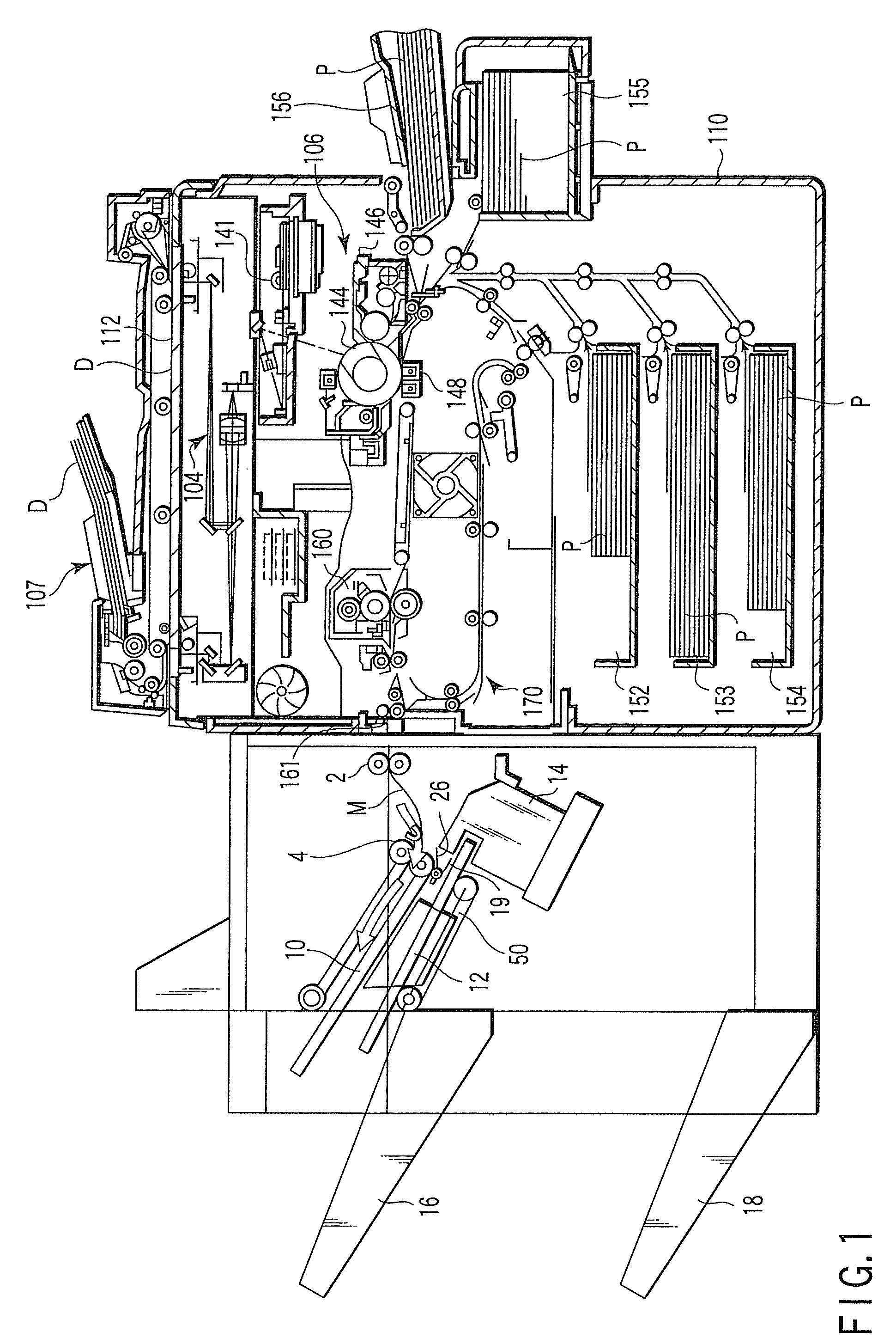
[0041]An overview of an image forming apparatus (a digital copying machine) and a post-processing apparatus according to an embodiment of the present invention arranged to be connected to a post-stage of the image forming apparatus are explained with reference to FIG. 1. In the image forming apparatus, an original placing stand 112 is provided on an upper surface thereof. An automatic document feeder 107 (hereinafter referred to as ADF) that automatically feeds an original D onto the original placing stand 112 is arranged on the original placing stand 112. After placing the original D on the ADF and performing predetermined setting (e.g., presence or absence of staple processing, a way of the staple processing, the number of copies, and a size of a sheet to be copied), a user presses a copy start switch. The original D...


PUM

PropertyMeasurementUnit
thicknessaaaaaaaaaa
angleaaaaaaaaaa
thickaaaaaaaaaa

Abstract

A bundle claw attached to a sheet conveyor belt includes a concave portion having a bottom surface for regulating a position of a trailing end of the sheets, and, in the bottom surface, a surface on a lower side that comes into contact with the sheet conveyor belt is formed deeper than a surface on an upper side to form the step portion between the surface on the lower side and the surface on the upper side. Therefore, when a small number of sheets are discharged from a processing tray to a stacking tray, a trailing end of the sheets is located on the lower surface side of the concave surface of the bundle claw, where the trailing end of the sheets should be originally located, and does not move to the upper surface side of the concave surface of the bundle claw.

Description

CROSS-REFERENCE TO RELATED APPLICATIONS[0001]This application claims the benefit of U.S. Provisional Applications No. 60 / 944,820, filed Jul. 19, 2007; No. 60 / 944,824, filed Jul. 19, 2007; and No. 60 / 944,825, filed Jul. 19, 2007.BACKGROUND OF THE INVENTION[0002]1. Field of the Invention[0003]The present invention relates to a sheet post-processing apparatus with an improved bundle claw of a sheet conveyor belt that conveys a sheet from a processing tray to a stacking tray and a sheet post-processing method.[0004]2. Description of the Related Art[0005]In a sheet post-processing apparatus, sheets stacked on a processing tray are conveyed to a stacking tray by using a sheet conveyor belt. The sheet conveyor belt is attached with a bundle claw. The bundle claw has a concave surface for regulating a position of a trailing end of stacked sheets to be conveyed and conveys the stacked sheets in an aligned state. Usually, the bundle claw has height sufficient for discharging a stapled sheet b...

Claims


Application Information

Patent Timeline
Patent Type & Authority Patents(United States)
IPC IPC(8): B65H39/00
CPCB65H29/52B65H2407/10B65H2511/152B65H2511/20B65H2511/415B65H2801/27B65H2220/01B65H2220/02B65H31/02B65H2301/4212B65H2301/4213B65H2405/11151B65H31/3081B65H2511/15
Inventor TERAO, YASUNOBUYAMAMOTO, MIKIO
Owner KK TOSHIBA
Why Eureka
Try Eureka