
Damper mechanism

a technology of adamant mechanism and a cylinder head, which is applied in the direction of friction lining, couplings, mechanical equipment, etc., can solve the problems of high hysteresis torque and achieve the effect of favored vibration damping performan

Inactive Publication Date: 2005-03-29
EXEDY CORP
View PDF12 Cites 0 Cited by
  • Summary
  • Abstract
  • Description
  • Claims
  • Application Information

AI Technical Summary

Benefits of technology

An object of the present invention is to achieve preferred vibration damping performance by causing the positive side and negative side of the torsion characteristic to differ appropriately.
Another object of the present invention is effect a difference in the positive side and negative side of the torsion characteristic using a simple structure.
This damper mechanism achieves a prescribed rigidity on the positive side (acceleration side) of the torsion characteristic and a rigidity lower than the prescribed rigidity on the negative side (deceleration) of the torsion characteristic. As a result, the damper mechanism can suppress rotational speed fluctuations that occur when a resonance point is passed on the positive side of the torsion characteristic and obtain a good damping rate over the entire negative side of the torsion characteristic. More specifically, the friction suppressing mechanism has a rotational gap only on the negative side of the torsional characteristic and does not produce high hysteresis torque with respect to small torsional vibrations. Consequently, if this damper mechanism is used in a FF vehicle or other vehicle for which the resonance peak remains in the region of practical engine speeds, the resonance peak on the positive side of the torsion characteristic can be made smaller while maintaining the tip-in and tip-out damping performance. Furthermore the noise level of the negative side can be held to a low level.
With this damper mechanism, torque is transmitted between the first rotary member and the second rotary member through the elastic member. When torsional vibrations are inputted, the elastic member is compressed and the frictional engaging section of the intermediate rotary member slides on the first rotary member, and the torsion vibrations are dampened and absorbed by means of a prescribed torsion characteristic. On one side of the torsion characteristic, the gap engaging part of the intermediate rotary member rotates integrally with the second rotary member and the frictional engaging section slides against the input and second rotary member. However, when small torsional vibrations are inputted and the first rotary member and second rotary member are rotating relative to each other within a prescribed angular range, the rotational gap prevents the elastic force of the elastic member from acting on the intermediate rotary member. As a result, the frictional engaging section does not slide against the second rotary member.
Conversely, on the other side of the torsion characteristic, the intermediate rotary member cannot rotate relative to the second rotary member even when small torsional vibrations are inputted and the first rotary member and the second rotary member are rotating relative to each other within a prescribed angular range. Consequently, the elastic member exerts an elastic force on the intermediate rotary member and, as a result, the frictional engaging section slides against the first rotary member. Thus, in this aspect, a simple structure can be used to form a friction suppressing mechanism that does not generate friction within a prescribed range of twisting angles on only one side of the torsion characteristic.

Problems solved by technology

More specifically, the friction suppressing mechanism has a rotational gap only on the negative side of the torsional characteristic and does not produce high hysteresis torque with respect to small torsional vibrations.

Method used


Image

  • Damper mechanism
  • Damper mechanism
  • Damper mechanism

Examples


Embodiment Construction

Selected embodiments of the present invention will now be explained with reference to the drawings. It will be apparent to those skilled in the art from this disclosure that the following description of the embodiments of the present invention is provided for illustration only, and not for the purpose of limiting the invention as defined by the appended claims and their equivalents.

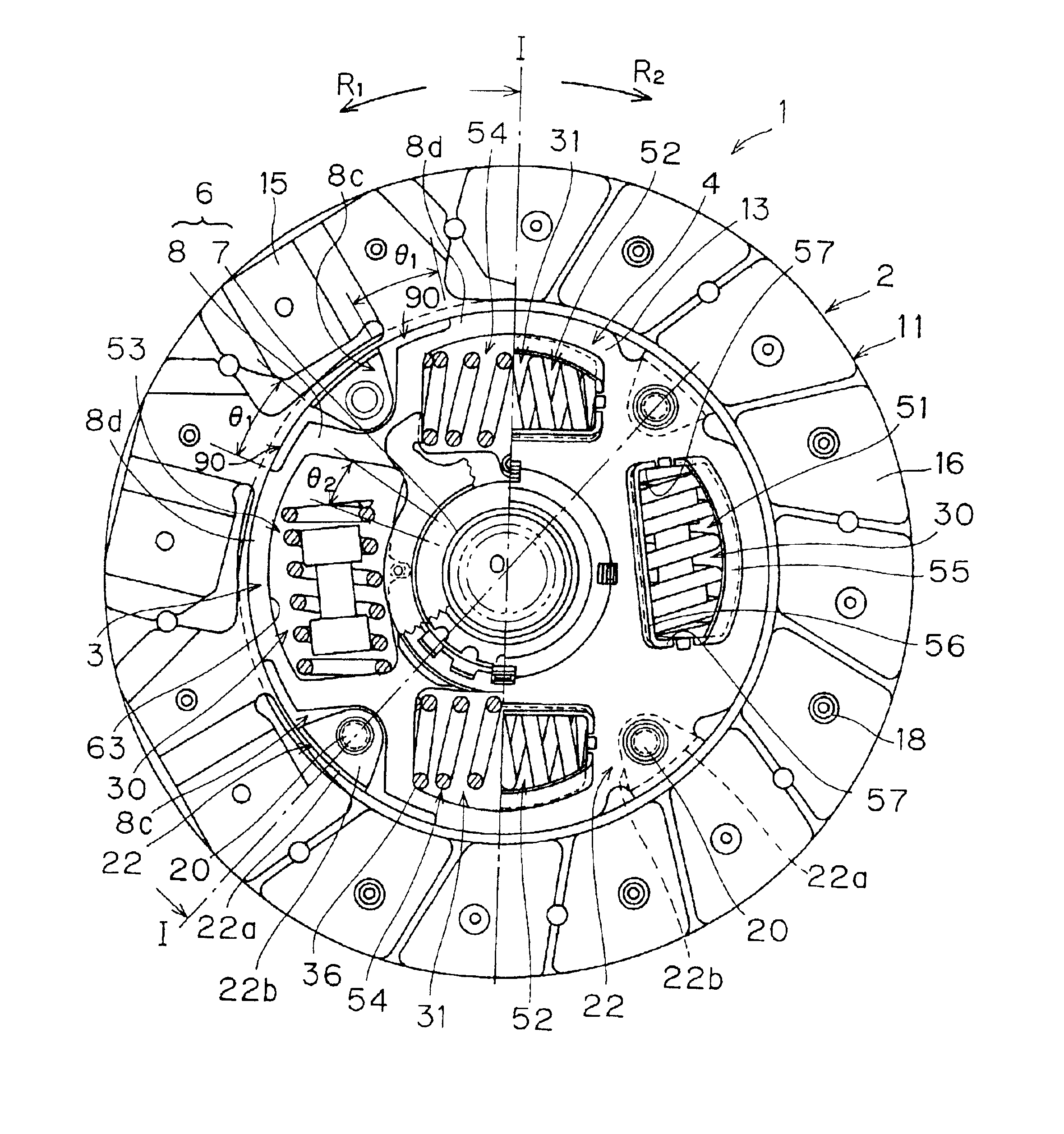
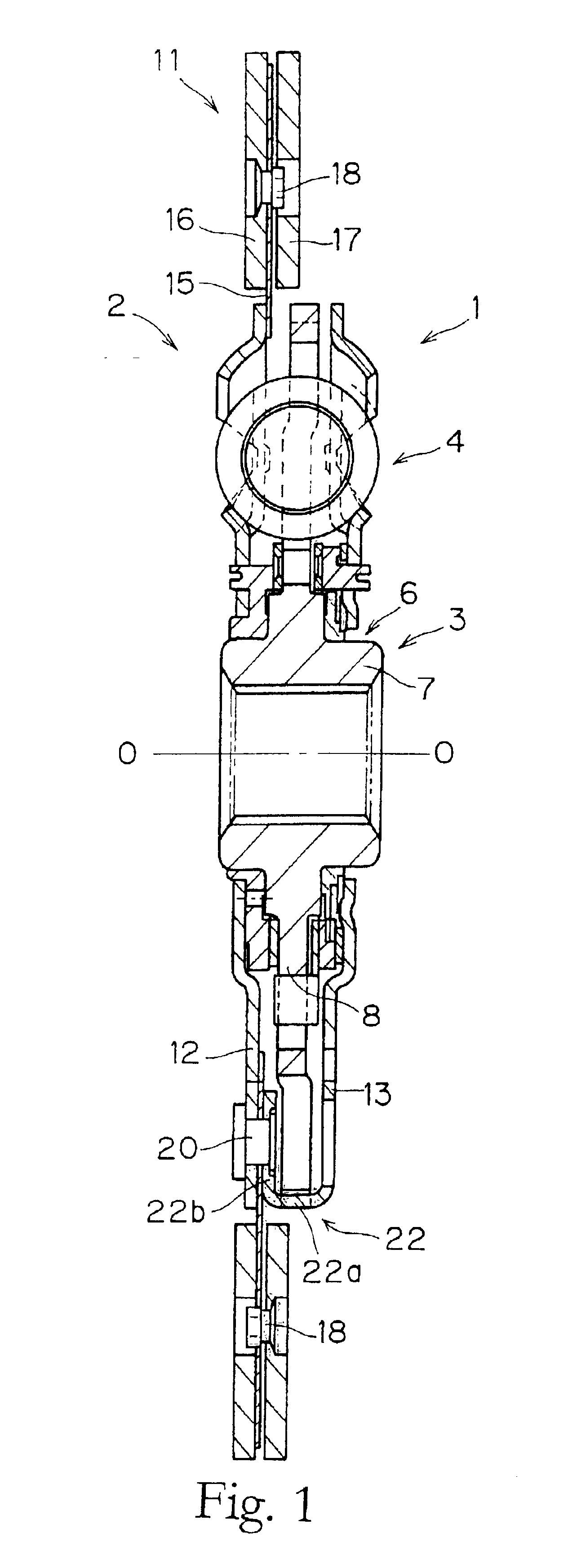
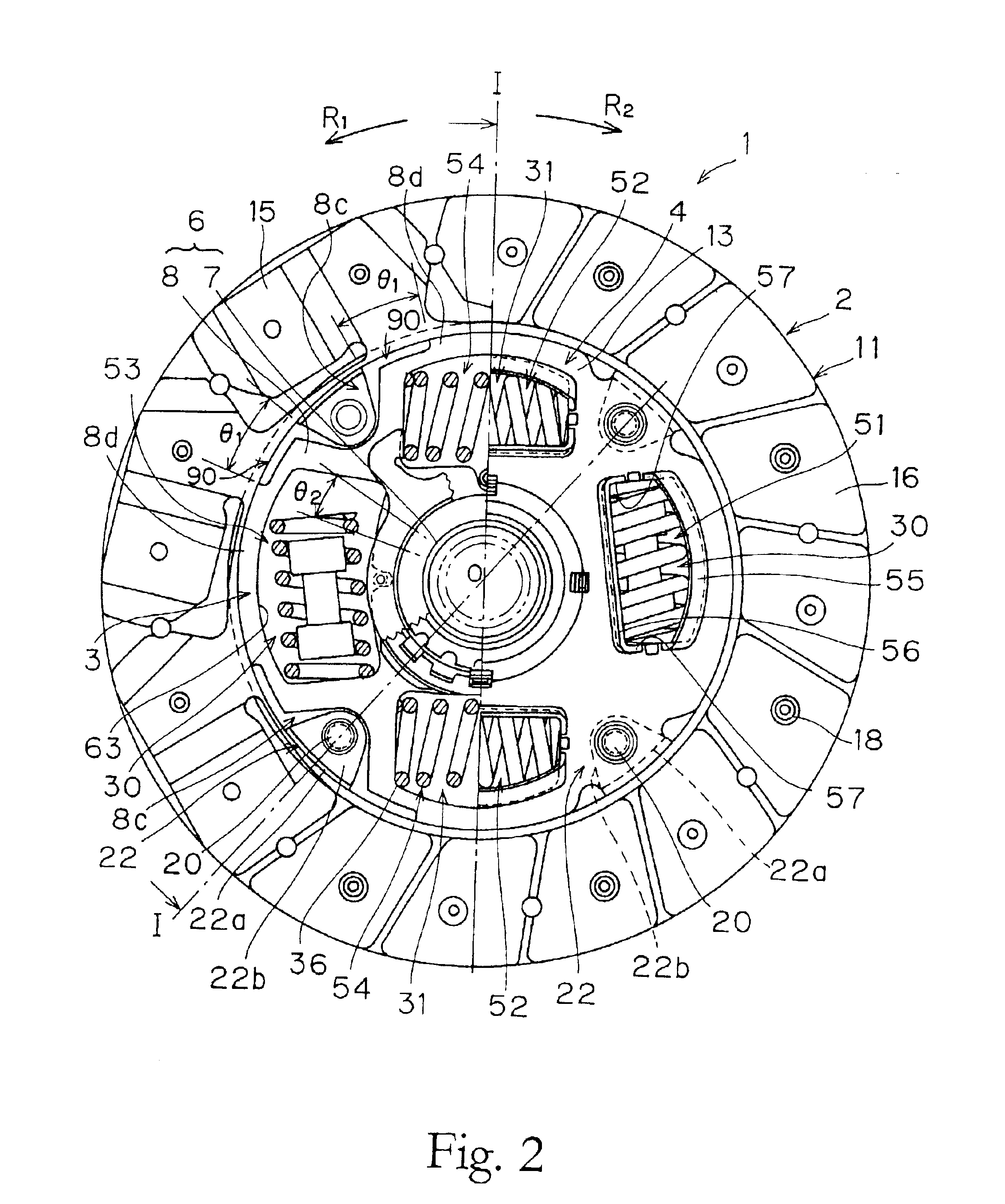
FIG. 1 is a cross-sectional view of a clutch disk assembly 1 in accordance with a preferred embodiment of the present invention. FIG. 2 is an elevational view of the same. The clutch disk assembly 1 is a power transmission device used in a clutch device of a vehicle (particularly an FF vehicle). The clutch disk assembly 1 has a clutch function and a damper function. The clutch function is provided to connect and disconnect torque by engaging the clutch disk assembly 1 with and disengaging it from a flywheel (not shown). The damper function is provided to absorb and damp torque fluctuations received from t...


PUM


Abstract

Coil springs 33 and 36 couple input and output rotary members 2 and 3 together such that they can rotate relative to each other. The coil springs 33 and 36 have a torsion characteristic having a positive region and a negative region that has a lower rigidity than the positive region. A second friction generating section 71 is arranged such that friction is generated rotationally-between the input rotary member 2 and the output rotary member 3 due to the elastic force of the coil springs 33 and 36 when the two rotary members 2 and 3 rotate relative to each other. A friction suppressing mechanism secures rotational gaps 91 and 92 on only the negative side of the torsion characteristic. These rotational gaps serve to prevent the elastic force of the coil springs 33 and 36 from acting on the second friction generating section 71 within a prescribed angular range.

Description

BACKGROUND OF THE INVENTION1. Field of the InventionThe present invention relates to a damper mechanism. More specifically, the present invention relates to a damper mechanism for absorbing and damping torsional vibrations while also transmitting torque.2. Background InformationConventional clutch disk assemblies used in vehicles have two basic functions. One function is to serve as a clutch for engaging with and disengaging from the flywheel. The other basic function is to serve as a damper mechanism for absorbing and damping torsional vibrations from the flywheel. In general, vehicle vibrations include idling-related noises (rattling sounds), traveling-related noises (rattling associated with acceleration and deceleration and muffled noises), and tip-in / tip-out (low frequency vibrations). The function of the clutch disk assembly as a damper is to eliminate these noises and vibrations.Idling-related noises are rattling noises that emit from the transmission when the gear shift is p...

Claims


Application Information

Patent Timeline
IPC IPC(8): F16F15/123F16F15/121F16F15/12F16F15/129
CPCF16F15/129F16F15/1236
Inventor AOKI, TATSUYUKIUEHARA, HIROSHI
Owner EXEDY CORP
Learn More