Zoom lens and imaging apparatus

a technology of zoom lens and imaging apparatus, applied in the field of zoom lens, can solve the problem of requiring a further increase in performance, and achieve the effect of reducing the number of zoom lenses

Active Publication Date: 2020-03-31
TAMRON
View PDF3 Cites 2 Cited by
  • Summary
  • Abstract
  • Description
  • Claims
  • Application Information

AI Technical Summary

Benefits of technology

[0062]To obtain the aforementioned advantageous effects, the GR group preferably includes at least one concave cemented surface on the object side, and at least one concave cemented surface on the image plane side. The concave cemented surface on the object side is preferred for correction of mainly the spherical aberration and longitudinal chromatic aberration related to longitudinal ray. The concave cemented surface on the image plane side is preferred for correction of mainly field curvature and chromatic aberration of magnification.
[0063]Further, from view of these points of achieving preferred optical performance in a large-aperture zoom lens, the GR group preferably includes at least two concave cemented surfaces having negative refractive power, on the object side. For example, the GR group preferably includes a cemented lens including a concave cemented surface on the object side and a concave cemented surface on the image plane side, i.e., a cemented lens consisting of three lenses cemented together, and a cemented lens including a concave cemented surface having negative refractive power, on the object side (a cemented lens consisting of two or more lenses cemented together).
[0065]In the zoom lens, the aperture stop can be arranged in any position. For example, although an aperture stop is arranged on the object side in the GR group (i.e., on the image side of the second lens group) in the example described below, in a zoom lens according to the present invention, an aperture stop may be arranged in any appropriate position, e.g., in the GR group or between the first lens group and the image plane, depending on the size of the imaging device, the range of the image viewing angle of the zoom lens, and the like. In this case, the following conditional expression (3) is preferably satisfied.
[0067]In the zoom lens, changing focal length is performed by varying intervals between the lens groups. In the present invention, varying intervals between the lens groups during changing focal length means that the interval between the first lens group and the second lens group and the interval between the second lens group and the GR group vary during changing focal length. If the GR group consists of a plurality of lens groups, intervals between the lens groups in the GR group vary during changing focal length. As long as the intervals between the lens groups changes during changing focal length, all the lens groups may be movable groups that move in the direction of the optical axis during changing focal length, or any one or more lens groups may be fixed groups.
[0069]The zoom lens employs the aforementioned configuration and satisfies at least one of the conditional expressions described below, thereby enabling favorable correction of chromatic aberration in the entire zoom range. Hence, the zoom lens achieves higher performance and has a smaller size than conventional ones, and has high optical performance.
[0071]The convex lens GpH included in the GR group satisfies the following conditional expression (1).1.85<ndpH<2.50  (1)Here,ndpH is the refractive index related to the d-line of the convex lens GpH

Problems solved by technology

However, in the zoom lens, variations in chromatic aberration during zooming are not adequately suppressed; therefore, a further increase in performance is required in the entire zoom range.

Method used


Image

  • Zoom lens and imaging apparatus
  • Zoom lens and imaging apparatus
  • Zoom lens and imaging apparatus

Examples


example 1

[0113](1) Configuration of Optical System

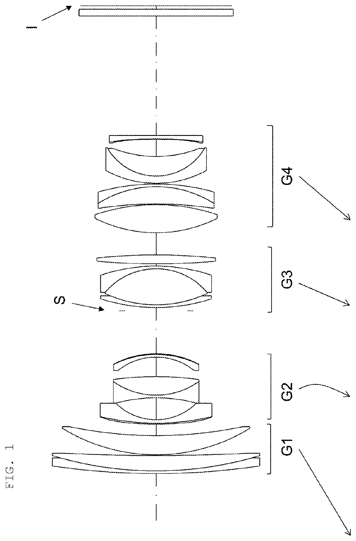
[0114]FIG. 1 is a cross-sectional view of a lens configuration example of a zoom lens of Example 1 of the present invention. The zoom lens consists of, in order from the object side, a first lens group G1 having positive refractive power, a second lens group G2 having negative refractive power, a third lens group G3 having positive refractive power, and a fourth lens group having positive refractive power, and changing focal length is performed by varying intervals between the lens groups. During changing focal length from the wide angle end to the telephoto end, the first lens group G1 moves toward the object, the second lens group G2 moves toward the object in such a manner that it draws a path protruding toward the image plane, the third lens group G3 moves toward the object, and the fourth lens group G4 moves toward the object. The moving paths of the lens groups are all different.

[0115]In the zoom lens of Example 1, the third lens group ...

example 2

[0128](1) Configuration of Optical System

[0129]FIG. 5 is a cross-sectional view of a lens configuration example of a zoom lens of Example 2 of the present invention. The zoom lens consists of, in order from the object side, a first lens group G1 having positive refractive power, a second lens group G2 having negative refractive power, a third lens group G3 having positive refractive power, and a fourth lens group having positive refractive power, and changing focal length is performed by varying intervals between the lens groups. During changing focal length from the wide angle end to the telephoto end, the first lens group G1 moves toward the object, the second lens group G2 moves toward the object in such a manner that it draws a path protruding toward the image plane, the third lens group G3 moves toward the object, and the fourth lens group G4 moves toward the object. The moving paths of the lens groups are all different.

[0130]In the zoom lens of Example 2, the third lens group ...

example 3

[0136](1) Configuration of Optical System

[0137]FIG. 9 is a cross-sectional view of a lens configuration example of a zoom lens of Example 3 of the present invention. The zoom lens consists of, in order from the object side, a first lens group G1 having positive refractive power, a second lens group G2 having negative refractive power, a third lens group G3 having positive refractive power, and a fourth lens group having positive refractive power, and changing focal length is performed by varying intervals between the lens groups. During changing focal length from the wide angle end to the telephoto end, the first lens group G1 to the fourth lens group G4 follow different paths to move toward the object.

[0138]In the zoom lens of Example 3, the third lens group G3 and the fourth lens group G4 constitute a GR group of the present invention. The 17th surface and the 18th surface included in the third lens group G3, and the 23rd surface and the 26th surface included in the fourth lens gr...


PUM


Abstract

An object of the present invention is to provide a zoom lens that can perform favorable correction of chromatic aberration in the entire zoom range, and can have higher performance and a smaller size than conventional ones; and an imaging apparatus including the zoom lens. To achieve the object, provided are a zoom lens and an imaging apparatus including the zoom lens. The zoom lens includes, in order from an object side: a positive first lens group G1; a negative second lens group G2; and a GR group including one or more lens groups. In the zoom lens, changing focal length is performed by varying intervals between the lens groups. The GR group includes convex lenses GpH and GpL satisfying predetermined conditional expressions. The convex lens GpH is the positive lens which is arranged second position or after from the object side in positive lenses in the GR group.

Description

CROSS-REFERENCE TO RELATED APPLICATION[0001]This application claims priority to Japanese Patent Application No. 2017-153069 filed Aug. 8, 2017, the disclosure of which is hereby incorporated in its entirety by reference.BACKGROUND OF THE INVENTIONField of the Invention[0002]This invention relates to a zoom lens suitable for imaging optical systems, such as film cameras, video cameras, and digital still cameras, and an imaging apparatus including the zoom lens.Description of the Related Art[0003]An imaging apparatus using a solid-state imaging device, such as a digital camera or a video camera, has been widely used. As pixel density in the solid-state imaging device increases, a higher performance has been required for imaging optical systems used in imaging apparatuses. In addition, with reductions in the sizes of imaging apparatuses, reductions in the sizes of imaging optical systems have been required.[0004]For interchangeable lens imaging apparatuses, such as single-lens reflex c...

Claims


Application Information

Patent Timeline
Patent Type & Authority Patents(United States)
IPC IPC(8): G02B15/14H04N5/225G02B7/04G02B15/173G02B13/06G02B27/00H04N5/335G02B7/14
CPCG02B15/145113G02B13/06H04N5/335G02B15/1461G02B15/14G02B15/1431G02B15/173H04N5/2254G02B7/04G02B7/14G02B27/0037G02B15/16G02B15/143105H04N23/55H04N25/00
Inventor OKADA, KEISUKE
Owner TAMRON
Why Eureka
Try Eureka