
Folding exercise rowing machine

a rowing machine and folding technology, applied in the field of exercise equipment, can solve the problems of large footprint of the machine, difficult storage of the machine, and large space occupation, and achieve the effect of convenient and quick folding, and sufficient resistan

Active Publication Date: 2011-01-04
COFFEY CALVIN T
View PDF22 Cites 45 Cited by
  • Summary
  • Abstract
  • Description
  • Claims
  • Application Information

AI Technical Summary

Benefits of technology

[0005]It is another object to provide an exercise rowing machine that can be easily and quickly folded down for storage, and can be just as easily folded out to an open condition for exercise use.
[0006]It is a further object to provide an exercise rowing machine that is more compact than earlier rowing machines that simulate realistic stroke action, and which nevertheless provide sufficient resistance for exercise and training purposes.
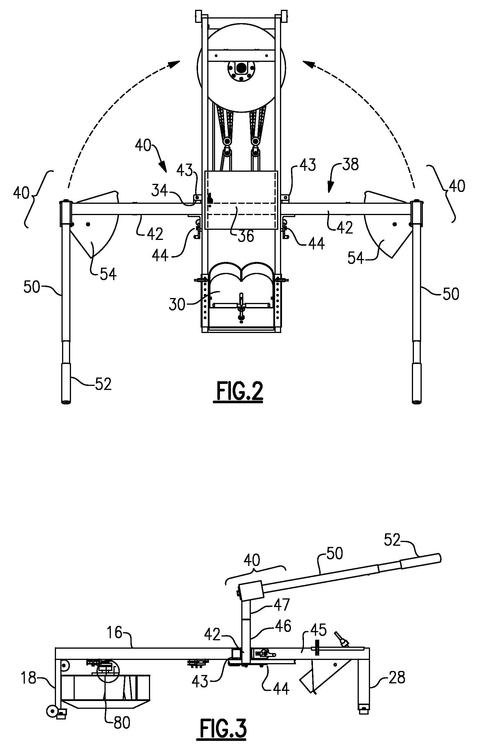
[0011]There are releasable latches that hold the transverse arms in their extended position during exercise use of the machine, but these are adapted to be released, and to permit the arms to swing rearwardly to their withdrawn position after use. The two cam members each have a thickness less than the vertical spacing between the flywheel and the rail members above it on the frame, and this permits the cam members to fit in the space between the flywheel and the seat rail members when the arms are in their withdrawn position, i.e., positioned alongside the frame.
[0014]The power cable arrangement includes a multiplier pulley arrangement that is situated between the power cable(s) and the drive chain that winds around the drive sprocket. The multiplier pulley arrangement imparts a motion multiplier effect, e.g., of 4:1, to the drive chain. The return means e.g., the an elastic member which anchored to said frame, can also have an associated multiplier pulley connected with the other end of the drive chain, and may favorably impart a motion multiplier effect of 4:1.

Problems solved by technology

The machines of this construction tend to have a large “footprint” and take up considerable space when they are not in use.
The machines are difficult to store also, unless the machine is disassembled.

Method used


Image

  • Folding exercise rowing machine
  • Folding exercise rowing machine
  • Folding exercise rowing machine

Examples


Embodiment Construction

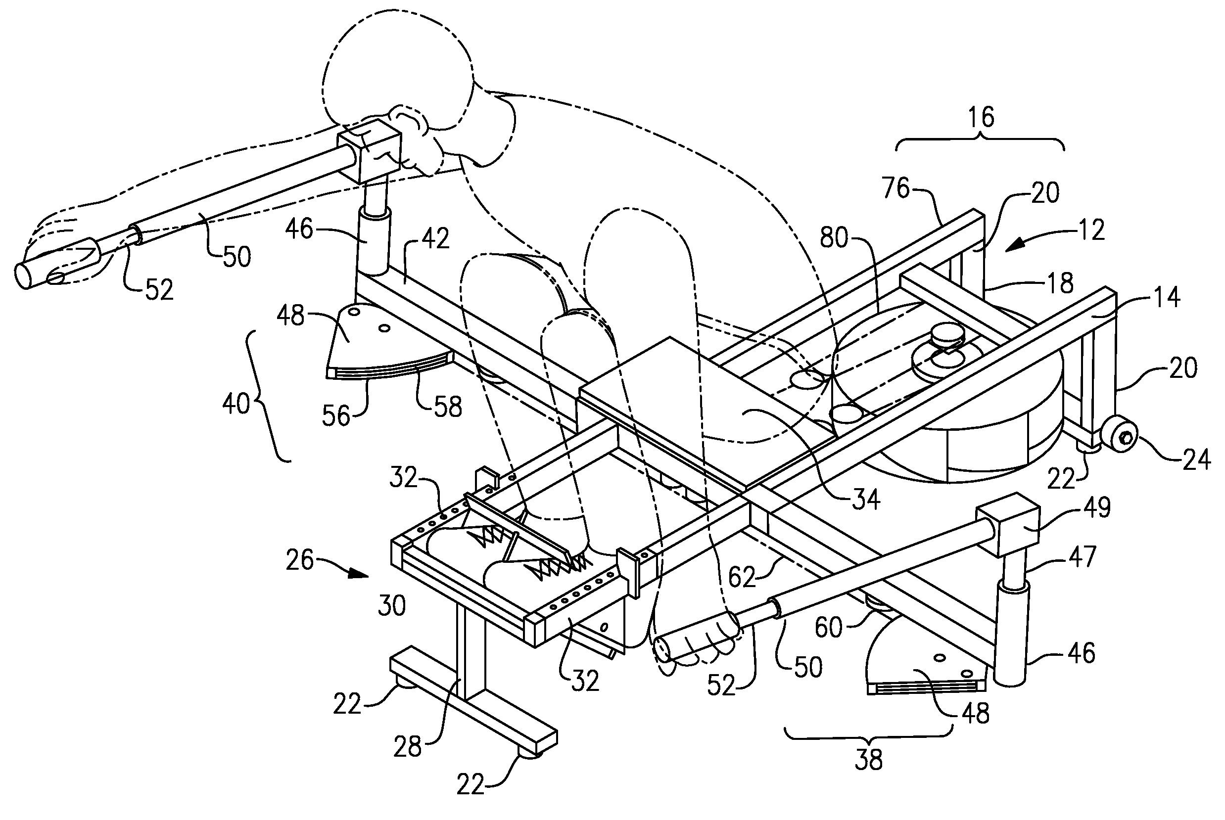
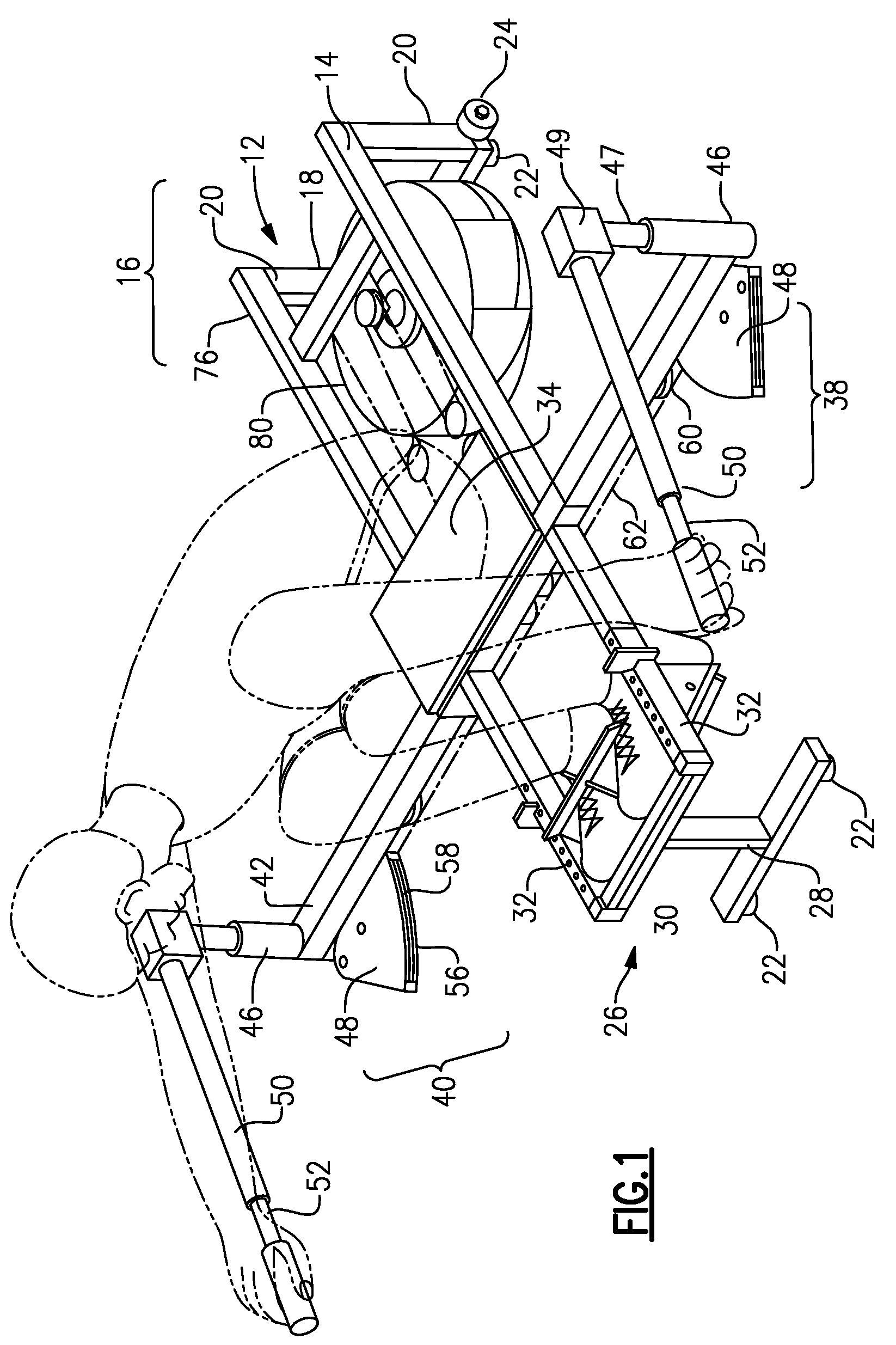
[0024]With reference to the Drawing, and initially to FIG. 1, and with additional reference to FIGS. 2, 3, 4 and 5, an exercise rowing machine 10 which embodies the present invention is shown in its normal use position, i.e., folded out and open. The machine 10 folded-in for storage, or to minimize the space taken up when not in use, is illustrated in FIGS. 6, 7, and 8.

[0025]The rowing machine 10 in this embodiment is formed of a frame 12, with longitudinal seat rails 14 and 16 disposed at the left and right sides of the frame. A proximal or rear end is situated behind the rower's position, with a pair of vertical risers 20, bumpers or rubber cushions 22 to contact the floor, and a pair of wheels or rollers 24 for facilitate moving the machine within the room. A distal or forward end 26 of the frame 12 has a vertical support leg 28, with bumpers 22 similar to those at the proximal end. A foot plate, i.e., stretcher or foot rest 30, is situated at the distal end, and may have heel cu...


PUM


Abstract

A folding exercise rowing or sculling machine has left and right fold-down oar assemblies, each formed of an arm hinged to the side of the frame, and a pivot at the end of the arm on which the oar and oarlock are mounted. A cam plate at a lower end of the pivot pulls a cable that drives the sprocket wheel of a flywheel mounted to the rear or proximal of the frame. The oar assemblies fold to rearward, with the cam wheels fitting in a space between the flywheel and the frame. Multiplier pulley assemblies couple the power cable and elastic cords to a drive chain that is wound around the sprocket.

Description

BACKGROUND OF THE INVENTION[0001]This invention relates to exercise equipment, and is more particularly concerned with a exercise rowing or sculling machines. The invention is specifically directed to a rowing or sculling machine that simulates the sweeping rowing motion characteristics of a rowing or sculling shell and imparts a resistance to the pull of oars similar to what is experienced in actual rowing or sculling on the water. The invention is also concerned with a rower or rowing machine that can be folded down to a compact shape for storage, and can be opened out for use in exercise.[0002]There are many types and styles of exercise rowing machines. One excellent example of a rowing machine that simulates the motions of actual rowing is described in Coffey U.S. Pat. No. 4,743,011. That patent also contains a discussion of many earlier rowing machines, including several that employ a flywheel with air vanes to impart resistance to the motions that simulate the stroke action of...

Claims


Application Information

Patent Timeline
IPC IPC(8): A63B69/08
CPCA63B21/157A63B22/0076A63B22/0087A63B21/0088A63B21/225A63B2210/50A63B2022/0035A63B2022/0082A63B2069/064
Inventor COFFEY, CALVIN T.
Owner COFFEY CALVIN T
Learn More