Knee joint prosthesis

a technology for knee joints and prostheses, applied in knee joints, prostheses, medical science, etc., can solve the problems of large surgical trauma to patients, failure of implanted prostheses, and reduced bone availability, so as to reduce surgical trauma, reduce the required size of surgical incisions, and reduce bone. the effect of volum

Inactive Publication Date: 2011-01-04
MAXX ORTHOPEDICS INC +1
View PDF15 Cites 26 Cited by
  • Summary
  • Abstract
  • Description
  • Claims
  • Application Information

AI Technical Summary

Benefits of technology

[0007]Another object of the present invention is to reduce surgical trauma by providing prosthetic implants that reduce the required size of surgical incisions and that reduce the amount of bone that must be removed during surgery when compared to prior art devices and surgical procedures.
[0008]Another object of the present invention is to reduce the leakage of bone cement into the joint space by providing an improved system for delivering bone cement to the interface between the implant and the bone.
[0009]Another object of the present invention is to reduce the likelihood of subsidence of implants by providing implants that require a minimal resection of bone such that the bone architecture is left intact and better able to adequately support the implants.

Problems solved by technology

Many of the prior art prostheses require large incisions to gain adequate access to the joint space to perform the surgery and the removal of a great deal of bone from the femur and tibia in order to accommodate the implant, thereby causing large amounts of surgical trauma to the patients and reducing the amount of bone available in the event that revision surgery is required.
In addition, the removal of too much bone may lead to failure of the implanted prosthesis due to subsidence of the implant into the underlying bone necessitating revision surgery to replace the failed implants.
When bone cement is injected into a portal located on a side wall of an implant, bone cement may leak from the portal into the joint space.
If left in the joint space, such excess or leaked bone cement may cause irritation.
On the other hand, inadequate amounts of bone cement may result in inadequate fixation resulting in the loosening of the implant.

Method used


Image

  • Knee joint prosthesis
  • Knee joint prosthesis
  • Knee joint prosthesis

Examples


Embodiment Construction

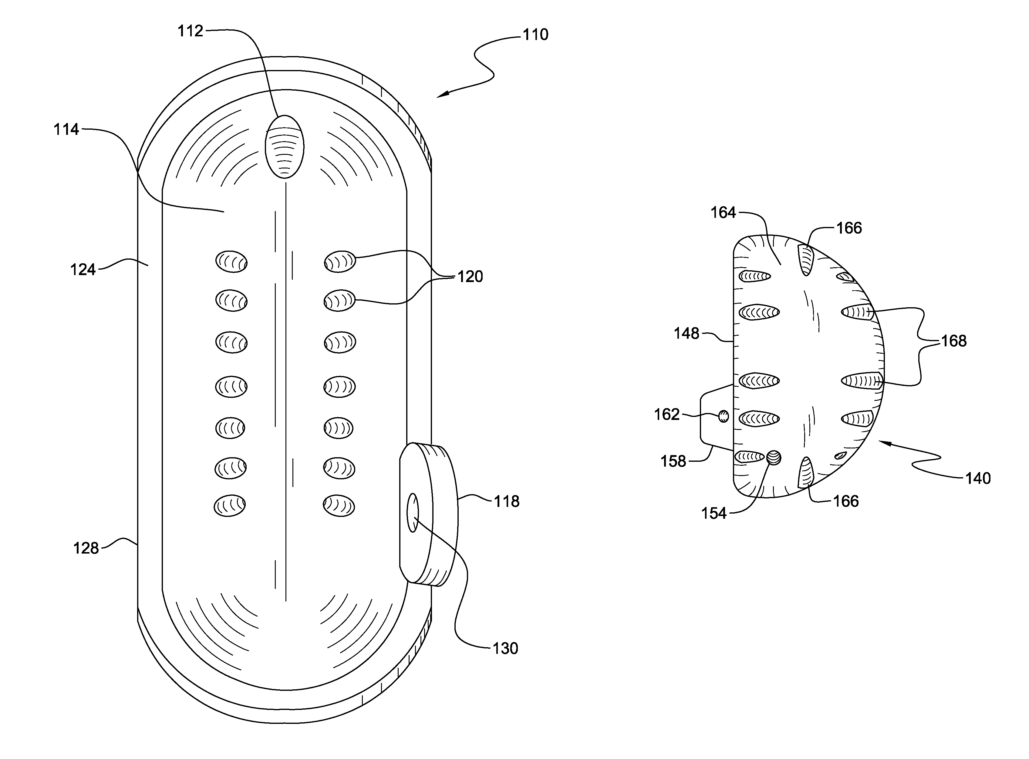
[0025]The present invention relates to prosthetic implants and, more particularly, to prostheses for human knee joints that are implantable by means of arthroscopic as well as open surgical techniques.

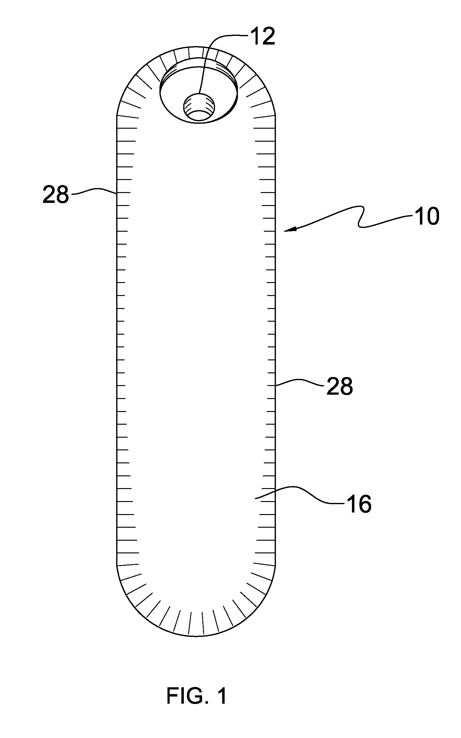
[0026]The femoral component 10 of the prosthesis of the present invention is illustrated in FIG. 1-5.

[0027]A distal view of the femoral component 10 is shown in FIG. 1. The femoral component 10 may have one or more through holes 12 passing through the distal surface of 16 of the femoral component 10 for receiving a bone screw or other fastener known in the art for attaching the femoral implant 10 to the distal end of a femur. The periphery 28 of the femoral component is continuous, smooth and unbroken by any openings.

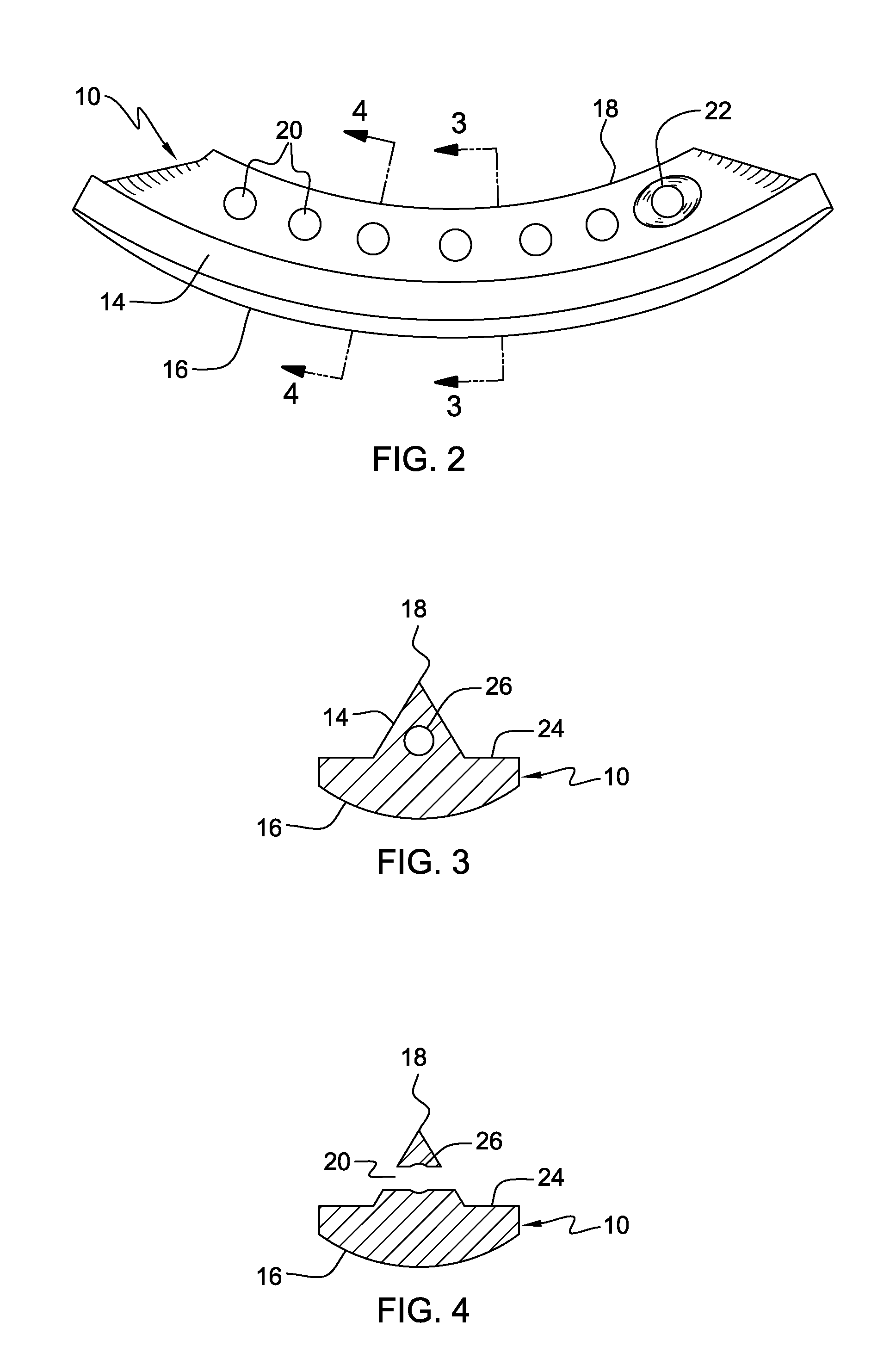
[0028]As shown in FIG. 2, the femoral component 10 comprises a curved body portion 14 having a convexly curved distal surface 16 and a concave proximal surface 18. A plurality of generally transverse bores or holes 20 are formed through the body portion 14 substantially pe...


PUM


Abstract

The present invention relates to a knee joint prosthesis including femoral and tibial components. The bodies of the components possess a network of channels which may be used to deliver bone cement to the component bone interface after the components are implanted. The body of the femoral component possesses a network of channels which is in communication with a bore on the distal surface of the component which may be used to deliver bone cement into the network of channels after the component is implanted. The body of the tibial component possesses a network of channels which is in communication with a bore on the proximal surface of the component which may be used to deliver bone cement into the network of channels after the component is implanted. The components are suitable for implantation using arthroscopic as well as open surgical procedures. The components may be used as unicondylar implants in either compartment of the knee or in both compartments of the knee.

Description

BACKGROUND OF THE INVENTION[0001]1. Field of the Invention[0002]The present invention relates to prosthetic implants and, more particularly, to prostheses for human knee joints that are implantable by means of arthroscopic as well as open surgical techniques.[0003]2. Description of Related Art[0004]It is common to provide implants to resurface worn articular surfaces of knees. Many of the prior art prostheses require large incisions to gain adequate access to the joint space to perform the surgery and the removal of a great deal of bone from the femur and tibia in order to accommodate the implant, thereby causing large amounts of surgical trauma to the patients and reducing the amount of bone available in the event that revision surgery is required. In addition, the removal of too much bone may lead to failure of the implanted prosthesis due to subsidence of the implant into the underlying bone necessitating revision surgery to replace the failed implants.[0005]Bone cement is typica...

Claims


Application Information

Patent Timeline
Patent Type & Authority Patents(United States)
IPC IPC(8): A61F2/38
CPCA61F2/38A61F2002/3895
Inventor CLARK, RON
Owner MAXX ORTHOPEDICS INC
Why Eureka
Try Eureka