Membrane for an electroacoustic transducer

a technology of electroacoustic transducers and membranes, which is applied in the direction of transducer diaphragms, loudspeaker diaphragm shapes, instruments, etc., can solve the problems of increased local loads on coils, poor sound quality, and distorted sound reproduction, so as to simplify the manufacturing of membranes and reduce the constant of planar springs , the effect of increasing the constant of planar springs

Inactive Publication Date: 2011-01-11
SOUND SOLUTIONS INTERNATIONAL COMPANY LTD
View PDF11 Cites 9 Cited by
  • Summary
  • Abstract
  • Description
  • Claims
  • Application Information

AI Technical Summary

Benefits of technology

[0018]In this way the performance of a membrane is dramatically increased. Since there are no or no substantial changes of the translatory spring constant along aforesaid line, the warping of the membrane is decreased, the stroke of the membrane is improved, and local peak loads on the membrane are avoided which results in improved sound reproduction, improved efficiency and improved lifetime.
[0027]Yet another very advantageous embodiment is achieved when said planar spring constants are determined by variation of depth, density, length, radius, and / or width of said corrugations. These are advantageous parameters of a corrugation to influence the planar spring constant of a membrane or its compliance respectively. The deeper, the longer, and the denser corrugations are the more compliant a membrane is, meaning that its planar spring constant is reduced. In contrast, a membrane is stiffer, meaning that its planar spring constant is increased, the wider a corrugation or the greater the radius at the bends of a corrugation is.

Problems solved by technology

The ever decreasing size and increased complexity of current devices lead to certain consequences for an inbuilt transducer.
Whereas circular speakers are fully symmetrical, rectangular and ovals speakers comprise some asymmetries which in turn lead to poor sound quality, which is to improved.
As a result, the translatory spring constant tsc is dramatically increased in the corners of the membrane 2 or in the curved sections b respectively which in turn leads to some unwanted consequences:warping of membrane 2, which in turn leads to distorted sound reproduction as well as to increased local loads on the coil 3.
This might damage the coil 3, in particular in case of a so-called self supporting coil;decreased stroke of membrane 2, which in turn leads to reduced volume or poor efficiency respectively;local peak loads within membrane 2, which in turn leads to buckling or breaking of membrane 2.
However, there is an unpredictable rise and drop in the graph of the translatory spring constant tsc at the border between the straight sections a and curved sections b, which again leads to the addressed consequences.
More recent investigations have revealed this unwanted effect.

Method used


Image

  • Membrane for an electroacoustic transducer
  • Membrane for an electroacoustic transducer
  • Membrane for an electroacoustic transducer

Examples


Embodiment Construction

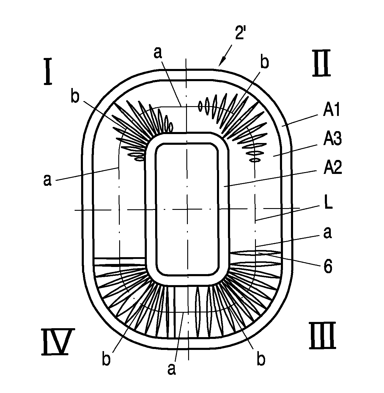
[0041]FIG. 5a shows a first set of four possible embodiments of an inventive membrane 2′ comprising corrugations 6, each embodiment in one of four quadrants I to IV. In a first quadrant I the length of corrugations 6 is varied, wherein all corrugations 6 start at the inner border of third area A3. In a second quarter II again the length of corrugations 6 is varied, but in contrast to the first embodiment the corrugations 6 are arranged in the middle of third area A3. In a third quadrant III the density of identical corrugations 6 is varied. Finally, the width of equally spaced corrugations 6 is varied in a fourth quadrant IV. It should be noted that the corrugations 6 are not arranged in the curved section b only, but also extend into the straight sections a.

[0042]FIG. 5b shows another set of four possible embodiments of an inventive membrane 2′ comprising corrugations 6, each embodiment again in one of four quadrants I to IV. Here the kind of corrugations 6 is the same for all four...


PUM


Abstract

A membrane (2′) for an electroacoustic transducer (1) is disclosed having a first area (A1), a second area (A2), which is arranged for translatory movement in relation to said first area (A1), and a third area (A3), which connects said first (A1) and said second area (A2), wherein local, planar spring constants (psc) along a closed line (L) within said third area (A3) encompassing said second area (A2), are determined in such a way that local, translatory spring constants (tsc) along said line (L) in a direction (DM) of said translatory movement are substantially constant or exclusively have substantially flat, mutual changes.

Description

FIELD OF THE INVENTION[0001]The invention relates to a membrane for an electroacoustic transducer having a first area, a second area, which is arranged for translatory movement in relation to said first area, and a third area, which connects said first area and said second area. The invention furthermore relates to a transducer comprising an inventive membrane and a device comprising an inventive transducer.BACKGROUND OF THE INVENTION[0002]The ever decreasing size and increased complexity of current devices lead to certain consequences for an inbuilt transducer. To optimize the ratio between space needed inside the device and sound-emanating area, speakers are more and more rectangular or oval instead of circular for example. Whereas circular speakers are fully symmetrical, rectangular and ovals speakers comprise some asymmetries which in turn lead to poor sound quality, which is to improved.[0003]FIGS. 1a and 1b show a first (left half) and a second (right half) embodiment of a rec...

Claims


Application Information

Patent Timeline
Patent Type & Authority Patents(United States)
IPC IPC(8): H04R7/00
CPCH04R7/20H04R2307/207H04R7/14
Inventor WINDISCHBERGER, SUSANNEWASINGER, HELMUTLUTZ, JOSEF
Owner SOUND SOLUTIONS INTERNATIONAL COMPANY LTD
Why Eureka
Try Eureka