Stanchion base shoe support for railings

a technology of stanchion and support, which is applied in the direction of balustrades, building types, constructions, etc., can solve the problems of requiring the technician to wear protective respirator equipment and hazardous cement dust, and achieve the effect of greater strength

Inactive Publication Date: 2011-01-11
HANSEN TRACY C
View PDF25 Cites 28 Cited by
  • Summary
  • Abstract
  • Description
  • Claims
  • Application Information

AI Technical Summary

Benefits of technology

[0009]The flat surface of the flange also aids the concrete contractor in floating the fresh concrete pour so that it maintains an even height from stanchion to stanchion. The stanchion embed typically has a removable film on the exposed face of the flange to keep concrete and other debris from fouling the threads on the device. A further advantage of the embedded stanchions is that, unlike concrete anchors, an embedded, or cast, element does not exert any stress or pressure to a concrete system. Moreover, field drilling of concrete creates hazardous cement dust and requires the technician to wear protective respirator equipment. The stanchion embed system eliminates all field drilling of concrete. A vent hole is formed in the flange plate to allow air to escape when inserting the stanchion into a core pocket that is already filled with grout. The stanchion tube portion is machined with a notch to act as a grout lock.
[0010]After the concrete is cured, workers apply the base shoe, securing it to the stanchions. This makes drilling and securing the base shoe simpler, easier and more accurate. Once the base shoe is installed, the railing system is built up in the normal manner.

Problems solved by technology

Moreover, field drilling of concrete creates hazardous cement dust and requires the technician to wear protective respirator equipment.

Method used


Image

  • Stanchion base shoe support for railings
  • Stanchion base shoe support for railings
  • Stanchion base shoe support for railings

Examples


Embodiment Construction

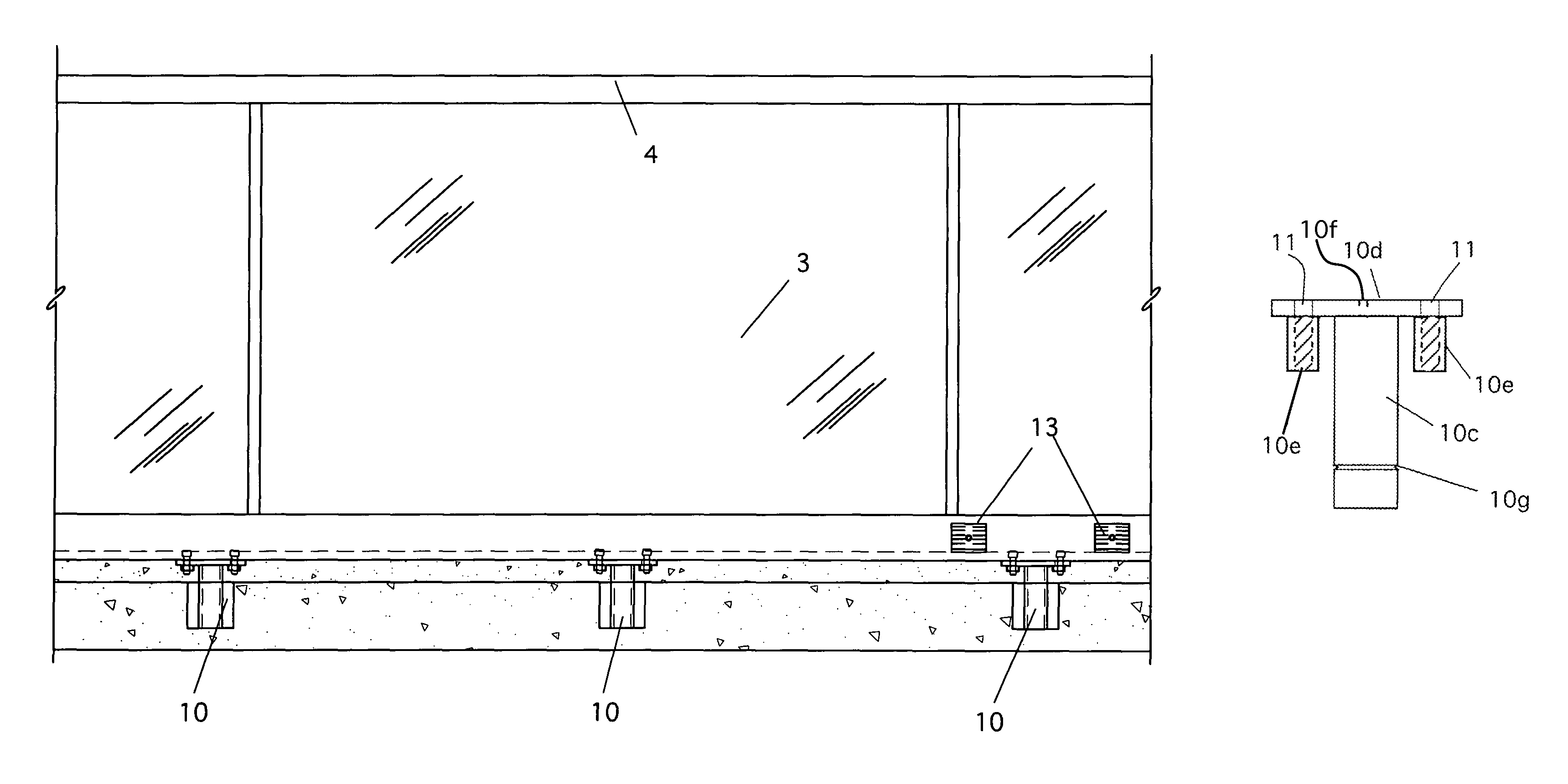
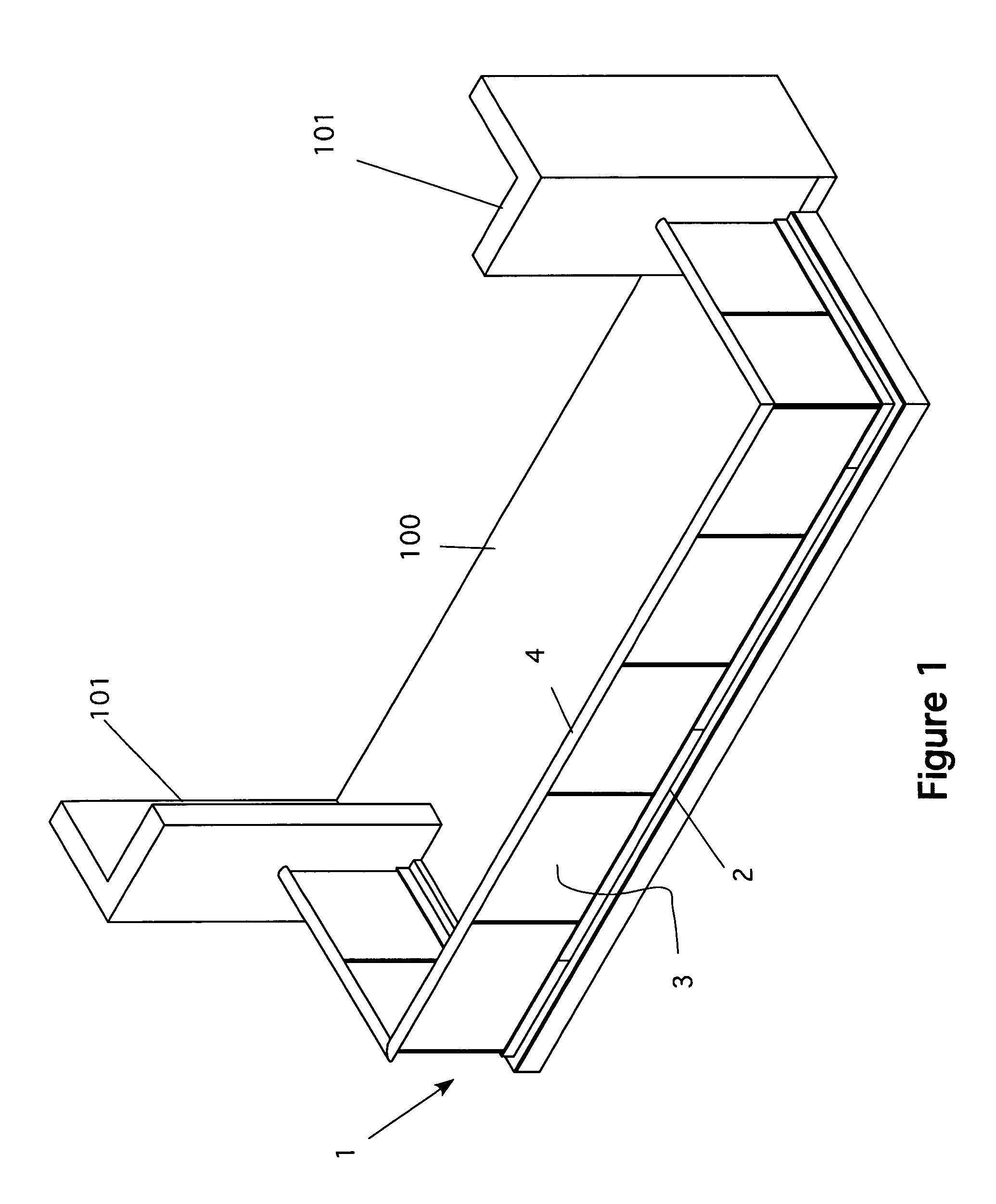
[0030]Referring now to FIG. 1, a perspective view of a railing incorporating the new design is shown. Here, a balcony 100 with building walls 101 is shown. The balcony is typically reinforced concrete. At the outer perimeter of the balcony is a railing 1. The railing has a base shoe 2, a number of infill panels 3 and a top rail 4. The infill panels 3 are typically glass, but can be any material ordinarily used for the purpose. The major difference between this railing system and others commonly used is that the base shoe 2 is not mounted directly into the concrete slab or curb. Rather, the base shoe 2 is secured to a number of stanchions that are embedded into the concrete.

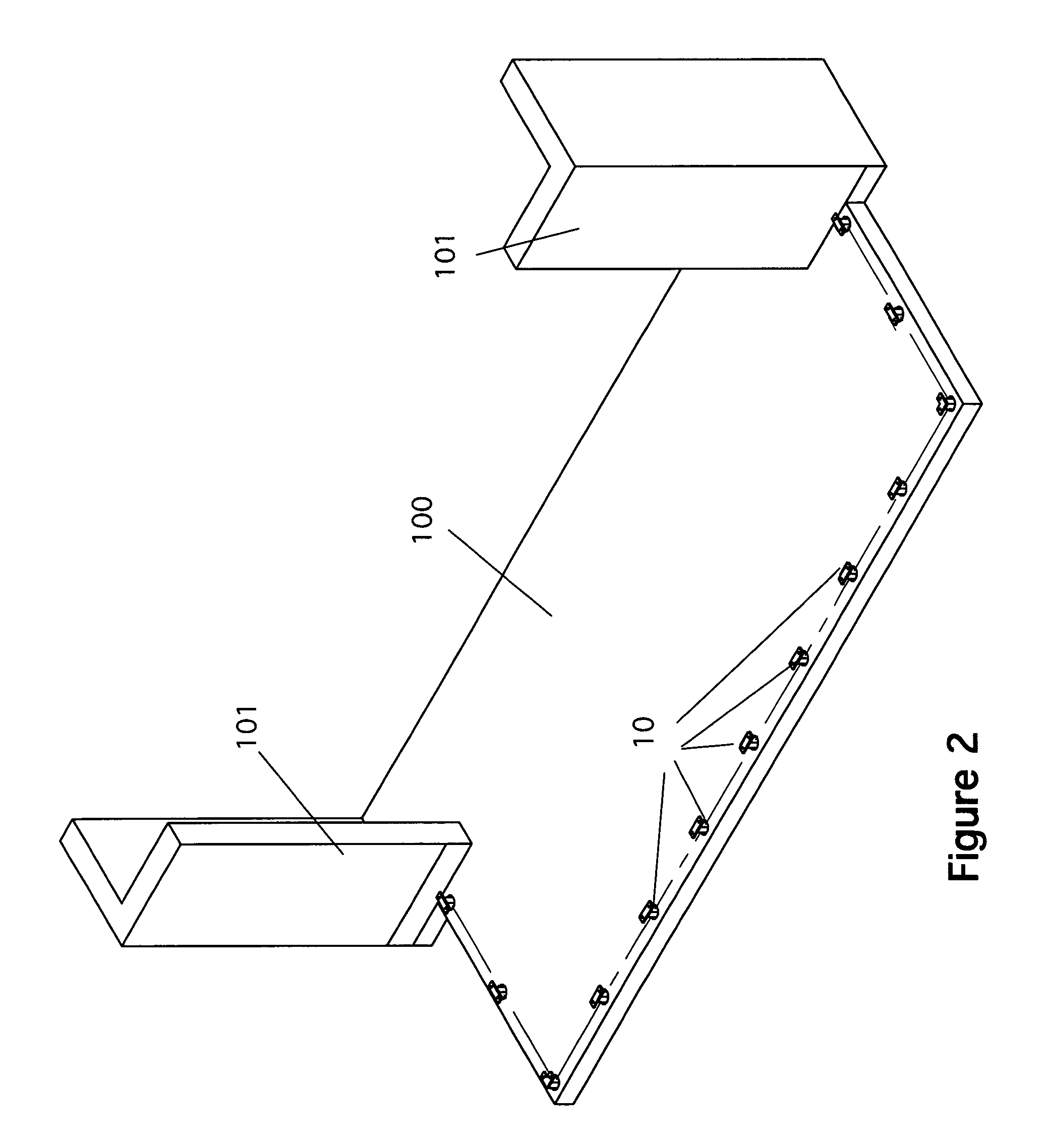
[0031]FIG. 2 is a perspective view of a balcony with a set of stanchions embedded in a concrete curb. Here, the balcony 100 is shown without the base shoe and railing in place. In this view, the stanchions 10 are clearly shown.

[0032]FIG. 3 shows the stanchions 10 embedded in a concrete curb in a plan view. Note th...


PUM


Abstract

A stanchion base shoe support for railings. The stanchions are set into a concrete slab or curb during the construction. Only the top surface of a mounting plate is exposed prior to mounting the base shoe extrusion. The stanchion is constructed from steel or a similar material. A flange plate at the top of the stanchion provides an easy place to mount a temporary support member when placing the stanchion into the concrete formwork. The stanchion system eliminates all field drilling of concrete. The stanchions have a top plate and cylindrical members that have a set of internal threads. After the concrete is cured, workers apply a base shoe, securing it to the stanchions. This makes drilling and securing the base shoe simpler, easier and more accurate. Once the base shoe is installed, the railing system is built up in the normal manner.

Description

CROSS REFERENCE TO RELATED APPLICATIONS[0001]Not ApplicableSTATEMENT REGARDING FEDERALLY SPONSORED RESEARCH AND DEVELOPMENT[0002]Not ApplicableBACKGROUND OF THE INVENTION[0003]1. Field of the Invention[0004]This invention relates to base shoes glass railing systems and particularly to base shoes having stanchion supports.[0005]2. Description of the Prior Art[0006]This new invention serves to overcome a series of installation issues currently experienced by those mounting a base shoe for structural glass railing systems to a concrete surface.[0007]The current state of the art, involves mounting the U-shaped base shoe to a concrete surface with some form of expansion bolt or self-tapping anchor. With this method, the installers must accurately drill both the extruded aluminum base shoe and the corresponding concrete balcony surface. The base shoe extrusion is typically drilled in factory conditions based on field dimensions, and the concrete surface is obviously drilled in the field u...

Claims


Application Information

Patent Timeline
Patent Type & Authority Patents(United States)
IPC IPC(8): E04H17/22
CPCE04F11/1836E04F11/1851E04F11/1853E04F2011/1823
Inventor HANSEN, TRACY C.
Owner HANSEN TRACY C
Why Eureka
Try Eureka