Light fixture assembly and LED assembly

a technology of led assembly and light fixture, which is applied in the direction of fixed installation, lighting and heating equipment, lighting support devices, etc., can solve the problems of poor luminous efficiency, inconvenient assembly, and inconvenient use of light fixture components,

Inactive Publication Date: 2011-01-11
KORRUS INC
View PDF97 Cites 152 Cited by
  • Summary
  • Abstract
  • Description
  • Claims
  • Application Information

AI Technical Summary

Benefits of technology

[0010]As a solution. exemplary embodiments of a light fixture assembly may transfer heat from the LED directly into the light fixture housing through a compression-loader member, such as a thermal pad, to allow for proper thermal conduction between the two. Additionally, exemplary embodiments of the light fixture assembly may allow end-users to upgrade their LED engine as LED technology advances by providing, a removable LED light source with thermal coupling without the need for expensive metal springs during manufacture, or without requiring the use of excessive force by the LED end-user to install the LED in the light fixture housing.
[0011]Exemplary embodiments of a light fixture assembly may include (1) an LED assembly and (2) an LED socket. The LED assembly may contain a first engagement member, and the socket may contain a second engagement member, such as angled slots. When the LED assembly is rotated, the first engagement member may move down the angled slots such that a compression-loaded thermal pad forms an interface with a light fixture housing. This compressed interface may allow for proper thermal conduction from the LED assembly into the light fixture housing. Additionally, as the LED assembly rotates into an engagement position, it connects with the LED socket's electrical contacts for electricity transmission. Thus, the use of the compressed interface may increase the ease of operation, and at the same time allow for a significant amount of compression force without the need of conventional steel springs. Further, the LED assembly and LED socket can be used in a variety of heat-dissipating fixture housings, allowing for easy removal and replacement of the LED. While in some embodiments the LED assembly and LED socket are shown as having a circular perimeter, various shapes may be used for the LED assembly and / or the LED socket.

Problems solved by technology

However, it is often difficult to combine both form and function into a light fixture assembly without compromising one or the other.
Incandescent bulbs, while inexpensive, are not energy efficient, and have a poor luminous efficiency.
Fluorescent bulbs and HID bulbs require a ballast to regulate the flow of power through the bulb, and thus can be difficult to incorporate into a standard light fixture assembly.
Moreover, LEDs generally fail by a gradual dimming over time, rather than abruptly burning out, as do incandescent, fluorescent, and HID bulbs.
While LEDs have various advantages over incandescent, fluorescent, and HID bulbs, the widespread adoption of LEDs has been hindered by the challenge of how to properly manage and disperse the heat that LEDs emit.
The performance of an LED often depends on the ambient temperature of the operating environment, such that operating an LED in an environment having a moderately high ambient temperature can result in overheating the LED, and premature failure of the LED.
Moreover, operation of an LED for extended period of time at an intensity sufficient to fully illuminate an area may also cause an LED to overheat and prematurely fail.
This often results in the creation of a light fixture assembly that is not upgradeable or replaceable within a given light fixture.

Method used


Image

  • Light fixture assembly and LED assembly
  • Light fixture assembly and LED assembly
  • Light fixture assembly and LED assembly

Examples


Embodiment Construction

[0033]Reference will now be made in detail to the exemplary embodiments consistent with the present invention, an example of which is illustrated in the accompanying drawings. Wherever possible, the same reference numbers will be used throughout the drawings to refer to the same or like parts. It is apparent, however, that the embodiments shown in the accompanying drawings are not limiting, and that modifications may be made without departing from the spirit and scope of the invention.

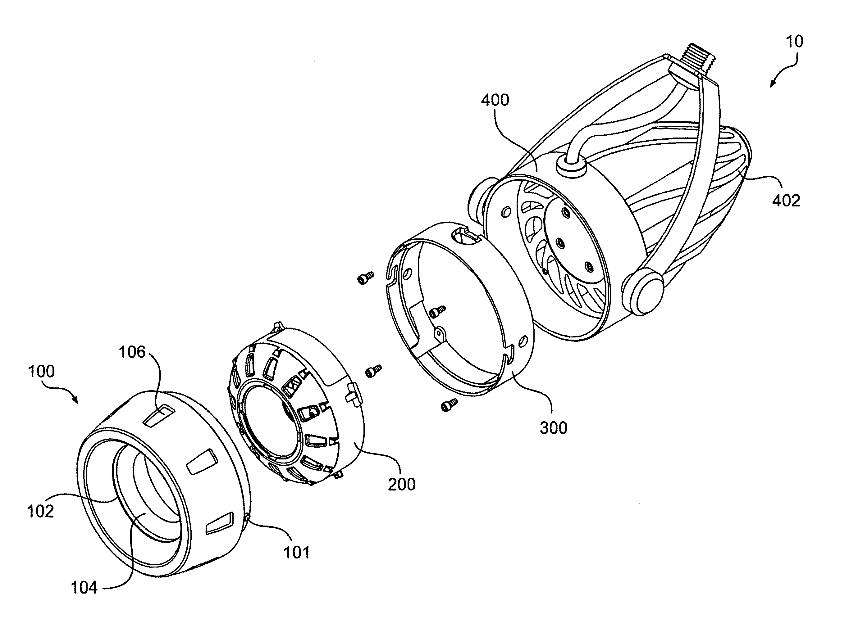
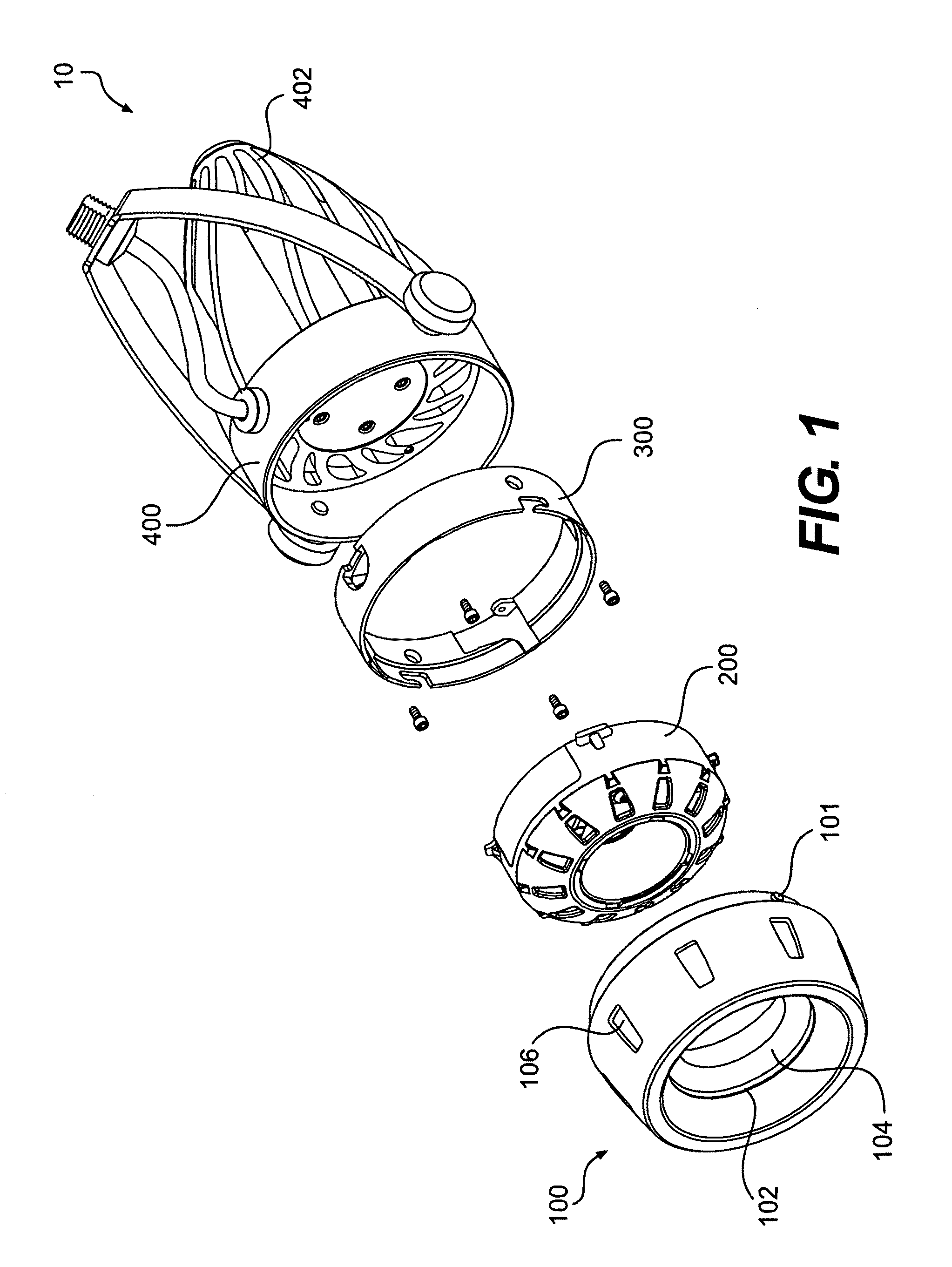
[0034]FIG. 1 is an exploded perspective view of a light fixture assembly 10 consistent with the present invention. Light fixture assembly 10 includes a front cover 100, a LED assembly 200, a socket 300, and a thermally-conductive housing 400.

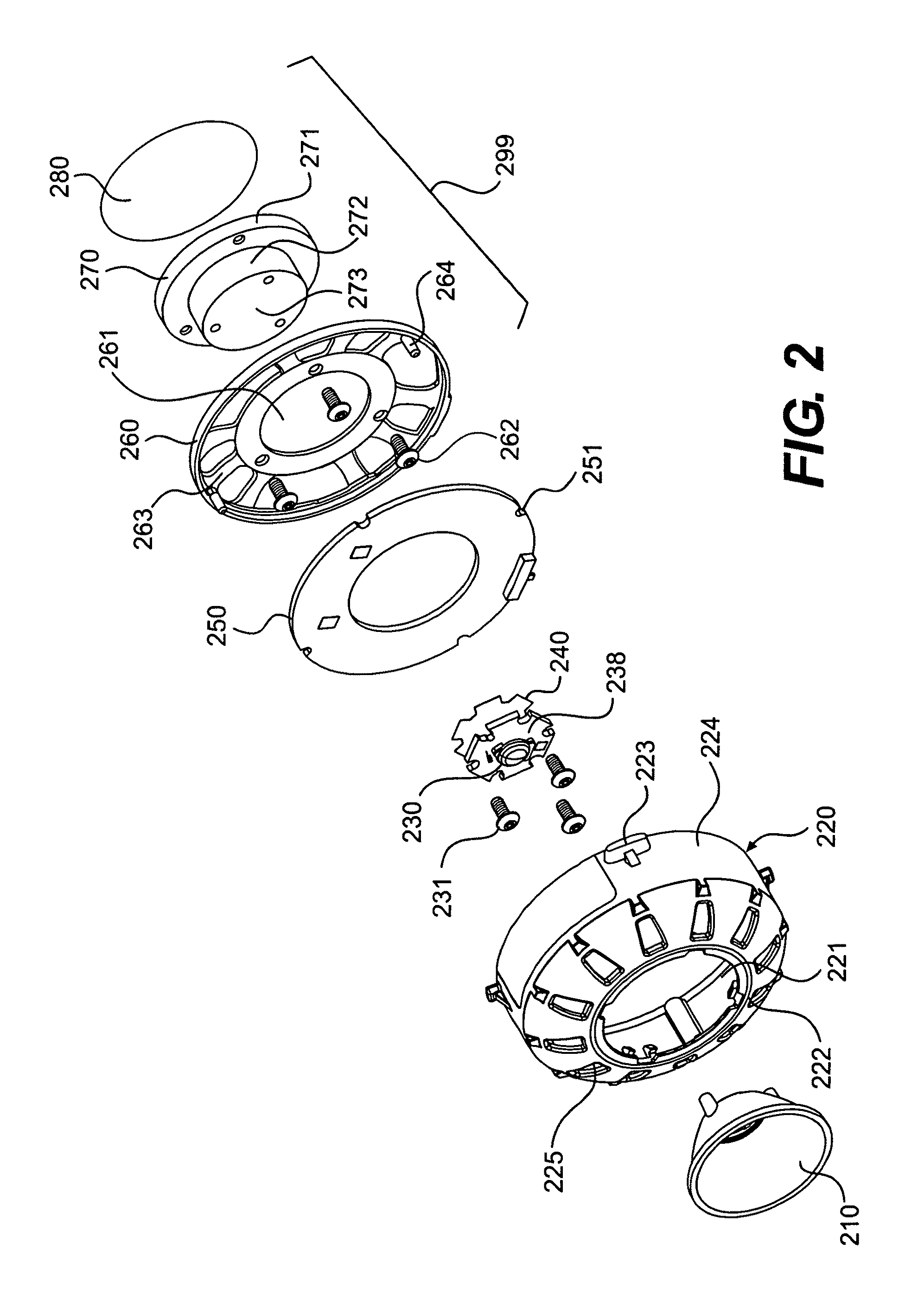
[0035]FIG. 2 is an exploded perspective view of LED assembly 200. LED assembly 200 may include a reflector, or optic, 210; a first shell 220; a lighting element, such as an LED 230; a thermally conductive material 240; a printed circuit board 250; a second shell 26...


PUM

PropertyMeasurementUnit
compression forceaaaaaaaaaa
thermal energyaaaaaaaaaa
thermally conductiveaaaaaaaaaa

Abstract

A removable light fixture assembly is provided. The light fixture assembly includes an LED lighting element and a compression element. Operation of the compression element from a first position to a second position generates a compression force which reduces thermal impedance between the LED assembly and a thermally-conductive housing.

Description

PRIOR APPLICATION[0001]This application claims the benefit of priority to U.S. Provisional Patent Application No. 61 / 064,282, filed Feb. 26, 2008, the entire contents of which are hereby incorporated by reference in their entirety.BRIEF DESCRIPTION[0002]1. Technical Field[0003]The present invention is directed to an LED assembly that can be connected thermally and / or electrically to a light fixture assembly housing.[0004]2. Background[0005]Light fixture assemblies such as lamps, ceiling lights, and track lights are important fixtures in many homes and places of business. Such assemblies are used not only to illuminate an area, but often also to serve as a part of the décor of the area. However, it is often difficult to combine both form and function into a light fixture assembly without compromising one or the other.[0006]Traditional light fixture assemblies typically use incandescent bulbs. Incandescent bulbs, while inexpensive, are not energy efficient, and have a poor luminous ef...

Claims


Application Information

Patent Timeline
Patent Type & Authority Patents(United States)
IPC IPC(8): F21V29/00
CPCF21V19/001F21V19/045F21V29/83F21V29/85F21V29/004F21V21/30Y10T29/49002F21Y2101/02F21Y2115/10F21V29/70F21V19/04
Inventor ALEXANDER, CLAYTONMUNDELL, BRANDON S.
Owner KORRUS INC
Why Eureka
Try Eureka