Device for dynamic stabilization of bones or bone fragments

a dynamic stabilization and bone technology, applied in the field of dynamic stabilization devices of bones or bone fragments, can solve the problems of implant looseness, obvious disadvantages, and conventional biocompatible plastics materials, and achieve the effects of reducing the load, reducing the load on the injured, and allowing certain flexibility of movemen

Active Publication Date: 2011-01-11
SYNTHES USA
View PDF153 Cites 9 Cited by
  • Summary
  • Abstract
  • Description
  • Claims
  • Application Information

AI Technical Summary

Benefits of technology

[0024]As a result of the compound construction it is also possible to reduce the dimensions of the longitudinal member consisting primarily of high-performance plastics material to a minimum, that is to say for it to be made substantially smaller than a longitudinal member were it to be made exclusively from biocompatible high-performance plastics material.
[0056]The posterior displacement of the point of rotation of the particular spine segment brought about in the case of a posteriorly implanted dynamic system brings about a reduction in the load on the injured intervertebral disc as already described hereinbefore and, in addition, allows axial deformation, which is important for the nutritional supply to the intervertebral disc.

Problems solved by technology

As already mentioned, conventional biocompatible plastics materials have the disadvantage that, after being subjected to mechanical pressure for a relatively long period, they yield to that pressure and actually “creep away” under that element of pressure.
There is accordingly a risk of the implant becoming loose with obviously disadvantageous consequences.

Method used


Image

  • Device for dynamic stabilization of bones or bone fragments
  • Device for dynamic stabilization of bones or bone fragments
  • Device for dynamic stabilization of bones or bone fragments

Examples


Embodiment Construction

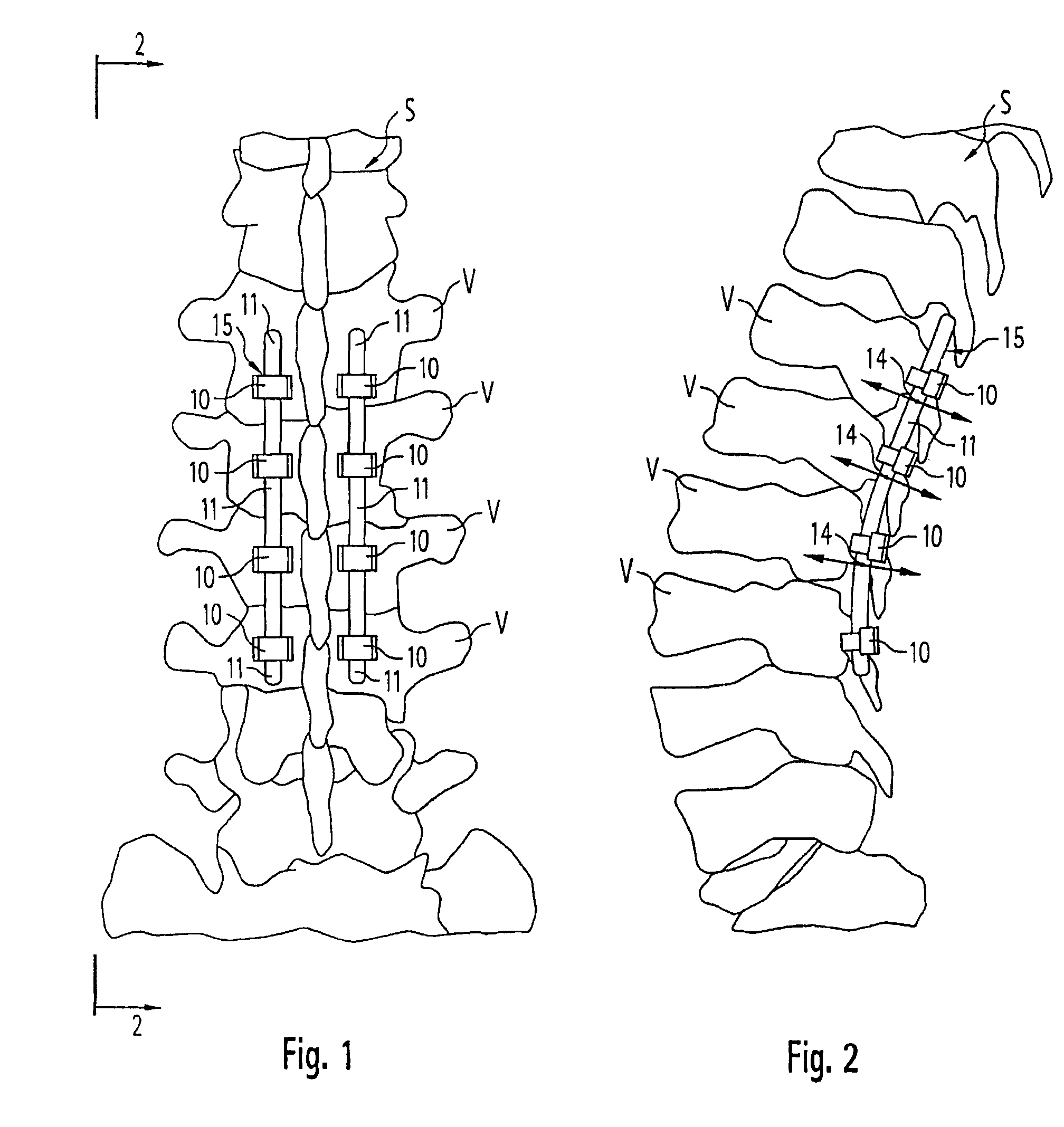
[0101]FIGS. 1 and 2 show part of a spine, reference letter “V” denoting the individual vertebra. Reference letter “S” denotes the spine. While the stabilization system is shown and described with reference to its use for spiral applications, it is understood and contemplated that the stabilization system may have applications in other areas of the body and in animals.

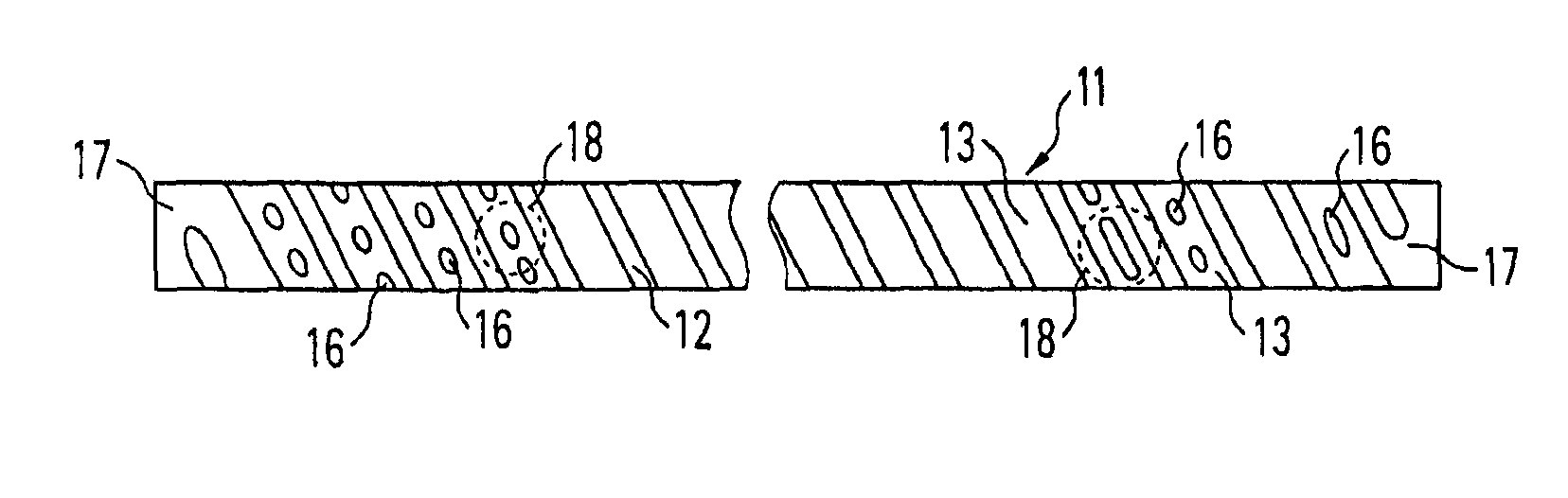
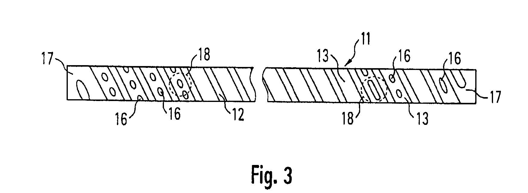
[0102]The individual vertebra “V” have been stabilized posteriorly; more specifically, for that purpose pedicle screws have been screwed into four vertebrae “V” from the posterior direction. The heads of the screws 10 each have accommodation apertures or accommodation slots or openings for accommodating a rod-shaped longitudinal member 11. The longitudinal member 11 is, as can be seen especially from the further figures, of generally round rod-shaped construction and is fixed by clamping in the heads of the pedicle screws 10. In that manner, a spine segment having four vertebrae “V” can be stabilized. The longitudinal m...


PUM


Abstract

A device for dynamic stabilization of bones or bone fragments comprising at least one anchor member for attachment to vertebrae having an opening configured to receive a longitudinal member; and the longitudinal member being viscoelastically deformable and having a predetermined bending resilience.

Description

CROSS-REFERENCE TO RELATED APPLICATIONS[0001]This is a continuation-in-part of pending International Application No. PCT / EP2005 / 003962, filed Apr. 14, 2005, which claims the benefit of German Patent Application No. 10 2004 048 938.6, filed Oct. 7, 2004, the entire contents of both of which are expressly incorporated herein by reference thereto.FIELD OF THE INVENTION[0002]The present invention relates to a device for dynamic stabilization of bones or bone fragments, especially vertebrae of the back, having at least one longitudinal member fixable to the vertebrae.BACKGROUND OF THE INVENTION[0003]Principal indications for dynamic, especially posteriorly performed, fixation are age- and / or disease-related decay (degeneration) of the integrity of the spine structures, inflammation and / or injuries in the region of the intervertebral disc, of the ligamentous apparatus, of the facet joints and / or of the subchondral bone.[0004]Posterior dynamic fixation systems have the function of modifyin...

Claims


Application Information

Patent Timeline
Patent Type & Authority Patents(United States)
IPC IPC(8): A61B17/70
CPCA61B17/7031A61B2017/00862
Inventor SCHLAEPFER, FRIDOLIN JOHANNES
Owner SYNTHES USA
Why Eureka
Try Eureka