Piezoelectric resonator including an acoustic reflector portion

a technology of acoustic reflector and resonator, which is applied in the direction of piezoelectric/electrostrictive device details, device details, generators/motors, etc., can solve the problem of easy peeling of film, and achieve the effect of improving resonance characteristics and stable quality

Active Publication Date: 2011-01-11
MURATA MFG CO LTD
View PDF11 Cites 86 Cited by
  • Summary
  • Abstract
  • Description
  • Claims
  • Application Information

AI Technical Summary

Benefits of technology

[0009]In order to solve the above-described problems, preferred embodiments of the present invention provide a piezoelectric resonator with stable quality and improved resonance characteristics.

Problems solved by technology

If an absolute value of compressive stress is large, film peeling occurs easily.

Method used


Image

  • Piezoelectric resonator including an acoustic reflector portion
  • Piezoelectric resonator including an acoustic reflector portion
  • Piezoelectric resonator including an acoustic reflector portion

Examples


example 1

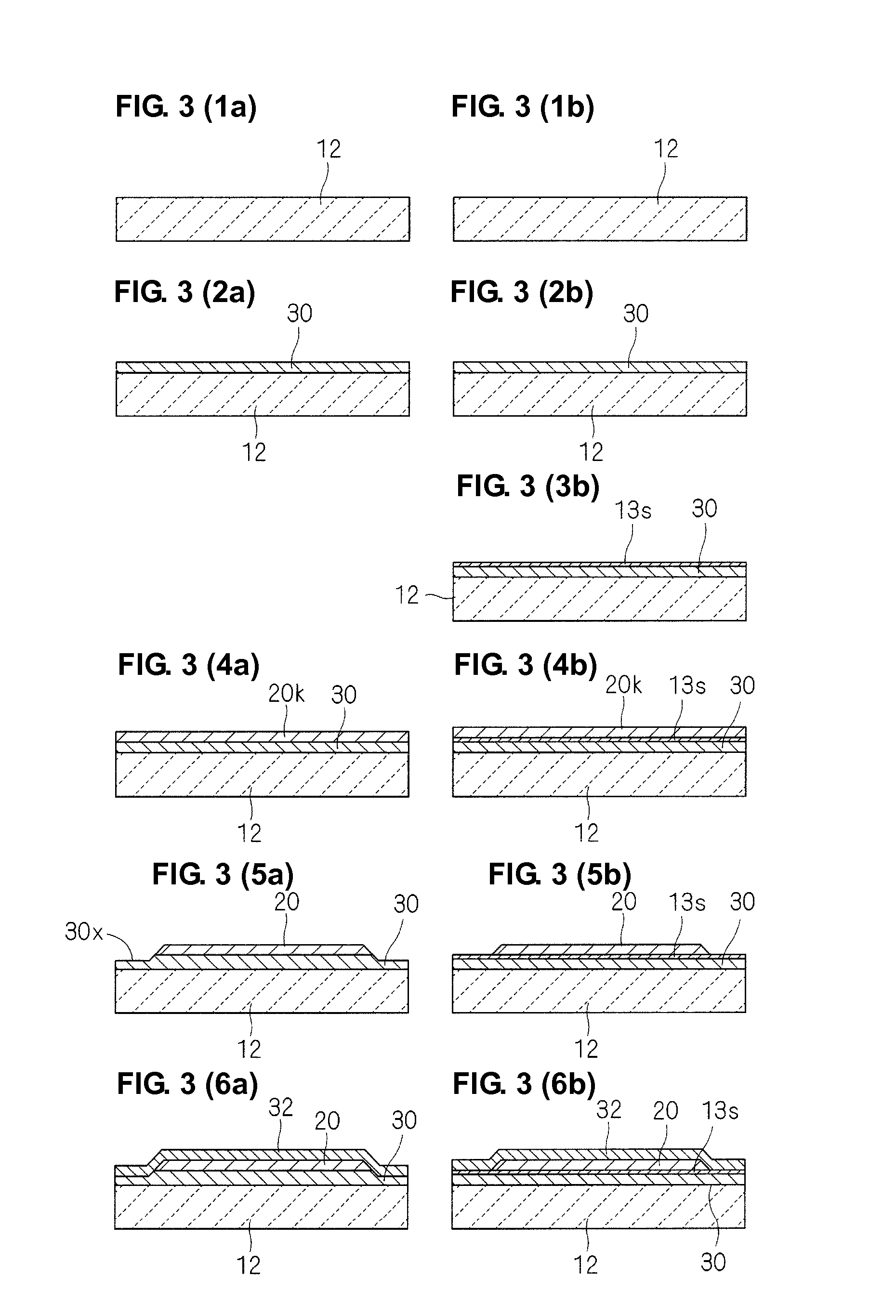
[0034]A piezoelectric resonator 10 of Example 1 will be described with reference to FIG. 1 to FIG. 4.

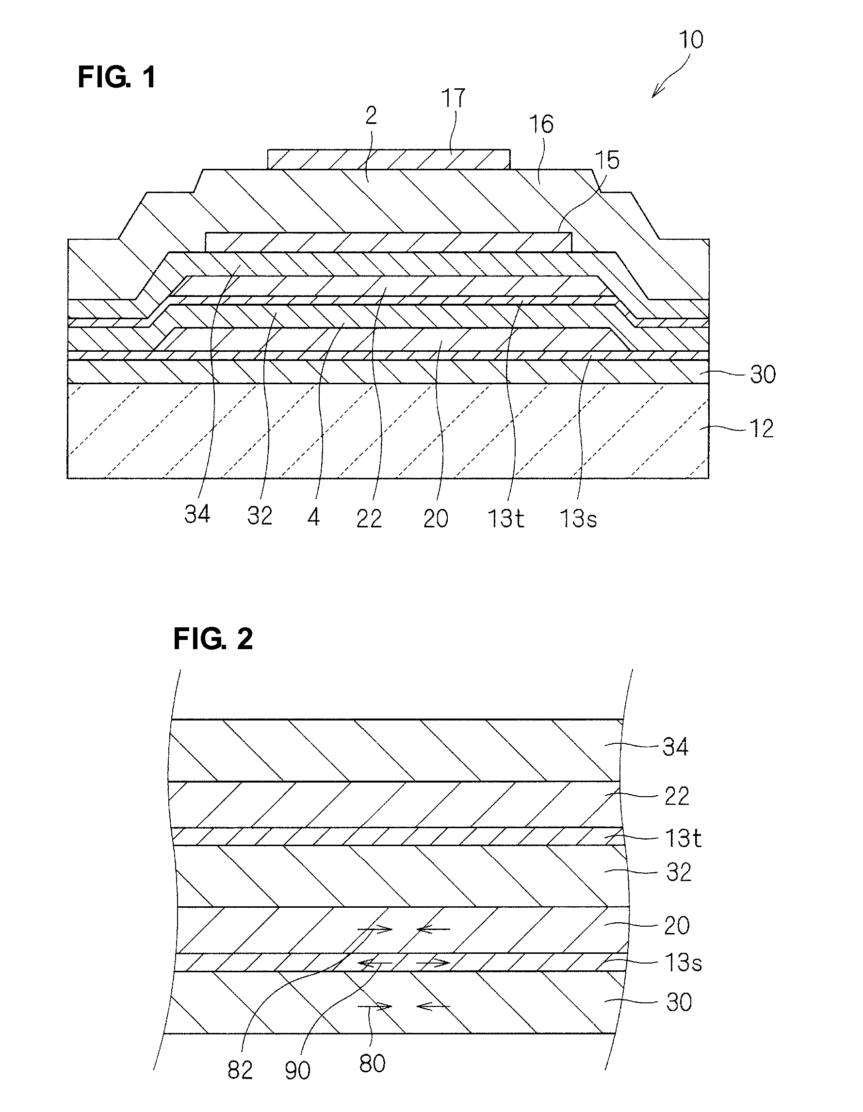
[0035]As indicated by a sectional view shown in FIG. 1, the piezoelectric resonator 10 preferably includes a vibration portion 2, which includes a piezoelectric thin film 16 sandwiched between an upper electrode 17 and a lower electrode 15, and the vibration portion 2 is acoustically separated from a substrate 12 with an acoustic reflector portion 4 therebetween.

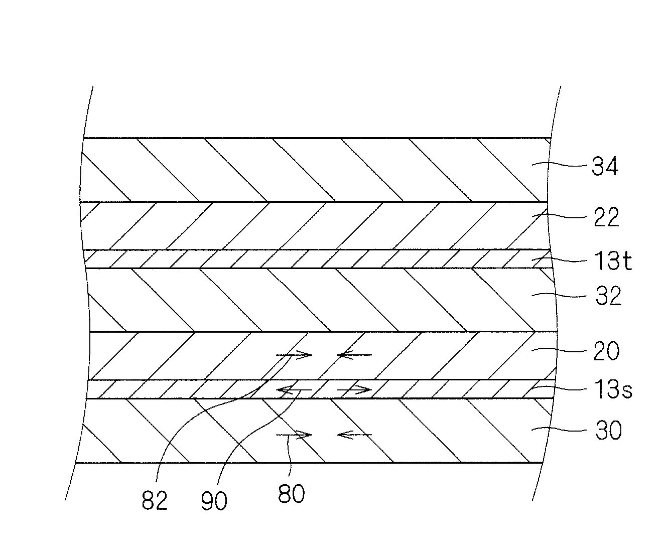
[0036]In the acoustic reflector portion 4, three layers of low acoustic impedance layers 30, 32, and 34 and two layers of high acoustic impedance layers 20 and 22 are disposed alternately, for example. The first low acoustic impedance layer 30 is in contact with the substrate 12 and the third low acoustic impedance layer 34 is in contact with the lower electrode 15.

[0037]Furthermore, an adjustment layer 13s is disposed between the first high acoustic impedance layer 20 and the first low acoustic impedance layer 30, and an adj...

example 2

[0068]A piezoelectric resonator 10a of Example 2 will be described with reference to FIG. 5.

[0069]As indicated by a sectional view shown in FIG. 5, the piezoelectric resonator 10a of Example 2 preferably has substantially the same configuration as that of the piezoelectric resonator 10 of Example 1 shown in FIG. 1, and the same effects as those in Example 1 are obtained. In the following description, the points different from Example 1 will be explained mainly, and the same constituent portions as those in Example 1 are represented by the same reference numerals.

[0070]The piezoelectric resonator 10a of Example 2 is different from Example 1 in configuration of an acoustic reflector portion 4a. Specifically, in the acoustic reflector portion4a of Example 2, adhesive layers 40 and 42 are disposed between the adjustment layers 13s and 13t and high acoustic impedance layers 20a and 22a. The adhesive layers 40 and 42 are patterned through etching or the like at the same time with the high...

example 3

[0073]A piezoelectric resonator 10b of Example 3 will be described with reference to FIG. 6.

[0074]As indicated by a sectional view shown in FIG. 6, the piezoelectric resonator 10b of Example 3 preferably has substantially the same configuration as that of the piezoelectric resonator 10 of Example 1 shown in FIG. 1, and the same effects as those in Example 1 are obtained.

[0075]As shown in FIG. 6, the piezoelectric resonator 10b of Example 3 is different from Example 1, and the width of the high acoustic impedance layer 20b on the substrate 12 side is larger than the width of the high acoustic impedance layer 22b on the vibration portion 2b side. Such high acoustic impedance layers 20b and 22b having different dimensions can be formed by using photomasks having different dimensions for individual high acoustic impedance layers 20b and 22b.

[0076]Consequently, the number of height differences formed on the uppermost surface 4s of the acoustic reflector portion 4b extending around the v...


PUM


Abstract

A piezoelectric resonator that achieves stable quality and improved resonance characteristics includes an acoustic reflector portion disposed between a substrate and a vibration portion, which includes a piezoelectric thin film sandwiched between a pair of electrodes, and a plurality of low acoustic impedance layers made of a material having relatively low acoustic impedance and a plurality of high acoustic impedance layers formed made of a material having relatively high acoustic impedance, the acoustic impedance layers being disposed alternately, and adjustment layers, which are disposed between the high acoustic impedance layers and the low acoustic impedance layers on the substrate sides of the high acoustic impedance layers and which have an acoustic impedance value intermediate between that of the high acoustic impedance layers and that of the low acoustic impedance layers. The low acoustic impedance layers and the high acoustic impedance layers have compressive stresses and the adjustment layers have a tensile stress.

Description

BACKGROUND OF THE INVENTION[0001]1. Field of the Invention[0002]The present invention relates to a piezoelectric resonator. In particular, the present invention relates to a piezoelectric resonator including an acoustic reflector portion to acoustically separate a vibration portion, which includes a piezoelectric thin film sandwiched between a pair of electrodes, from a substrate and to support the vibration portion.[0003]2. Description of the Related Art[0004]Previously, piezoelectric resonators (Bulk Acoustic Wave resonators or BAW resonators) taking advantage of thickness vibration of a piezoelectric thin film and piezoelectric filters formed from the piezoelectric resonators include a type provided with a cavity and a type provided with an acoustic reflector portion to acoustically separate a vibration portion, which includes a piezoelectric thin film sandwiched between a pair of electrodes, from a substrate and to support the vibration portion.[0005]Regarding the latter type, a...

Claims


Application Information

Patent Timeline
Patent Type & Authority Patents(United States)
IPC IPC(8): H01L41/04H01L41/08H01L41/09H01L41/187H01L41/22H03H9/17
CPCH03H3/02H03H9/02133H03H9/175
Inventor UMEDA, KEIICHI
Owner MURATA MFG CO LTD
Why Eureka
Try Eureka