
Method for estimating three-dimensional position of human joint using sphere projecting technique

a projecting technique and human joint technology, applied in the field of three-dimensional position estimation of human joints using sphere projecting techniques, can solve the problems of limited movement of figures, increased overall cost of systems, and difficult to accurately measure the position of joints using, and achieve the effect of accurate determination

Inactive Publication Date: 2011-01-11
ELECTRONICS & TELECOMM RES INST
View PDF23 Cites 8 Cited by
  • Summary
  • Abstract
  • Description
  • Claims
  • Application Information

AI Technical Summary

Benefits of technology

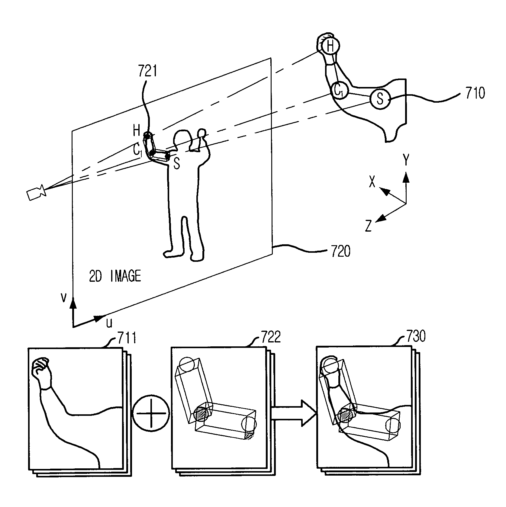
[0006]It is, therefore, an object of the present invention to provide a method for estimating a 3D position of a human joint, e.g., an elbow, knee, shoulder, etc., which uses an actual distance ratio to position the joint on a spherical surface to generate a virtual sphere, and position the virtual sphere in a 2D image of the moving figure to estimate the intersecting point as the 3D position of the joint, allowing the position of a human joint to be accurately determined three-dimensionally in real time.
[0008]The present invention provides a method for accurately detecting 3D positions of human joints in real time without using attached markers or sensors, so that it can detect the 3D position of an elbow joint using marker-free motion capture.

Problems solved by technology

In this technique, however, because a moving figure is filmed wearing clothes on which the markers are fitted, the movements of the figure are restricted.
Also, because special lighting must be installed in addition to the markers and sensors for accurate position measurements, the overall cost of the system increases.
In this technique, however, it is difficult to accurately measure position of joints using only color data that differentiates between bodily portions.
However, in this conventional method, there are bodily end-effectors such as shoulders hips, etc., that cannot be accurately detected using inverse kinematics.
Therefore, the human joint positions are difficult to accurately measure using computer vision technology.

Method used


Image

  • Method for estimating three-dimensional position of human joint using sphere projecting technique
  • Method for estimating three-dimensional position of human joint using sphere projecting technique
  • Method for estimating three-dimensional position of human joint using sphere projecting technique

Examples


Embodiment Construction

[0019]The above-described objects, characteristics, and advantages of the invention will become apparent from the following description of the embodiments with reference to the accompanying drawings, which is set forth hereinafter. The invention may, however, be embodied in many different forms and should not be construed as being limited to the embodiments set forth herein; rather, these embodiments are provided to fully convey the concept of the invention to those skilled in the art. Also, in the description of the present invention, descriptions of related and published skills shall be omitted when they are deemed to induce unclearness in the purpose of the inventive description.

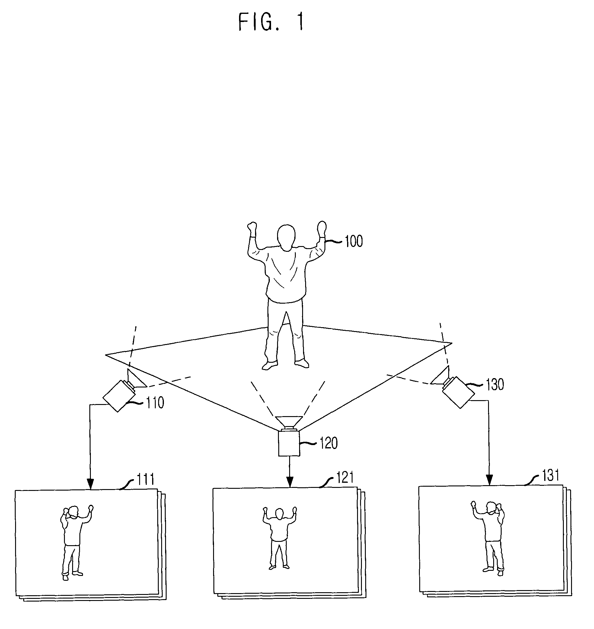
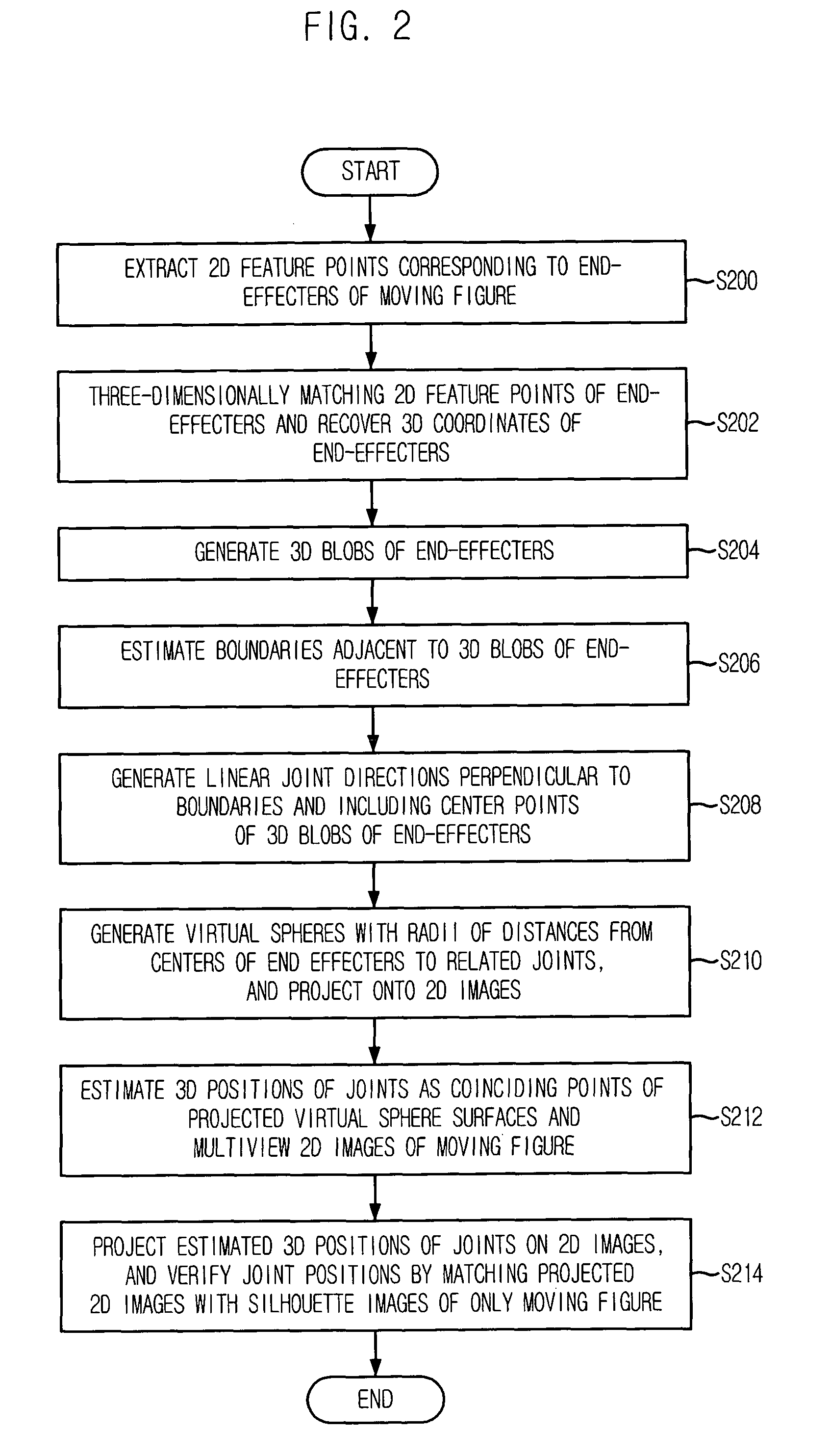
[0020]FIG. 1 is a view of a camera shot using marker-free motion capture in accordance with an embodiment of the present invention, and FIG. 2 is a flowchart illustrating a method for estimating 3D position of human joint using a sphere projecting technique in accordance with an embodiment of the present ...


PUM


Abstract

A method for estimating three-dimensional positions of human joints includes the steps of: a) marker-free motion capturing a moving figure for obtaining a multiview 2D image of the moving figure, and extracting a 2D feature point corresponding to a bodily end-effector; b) three-dimensionally matching the 2D feature point corresponding to the bodily end-effector, and recovering the 3D coordinates of the bodily end-effector; c) generating a 3D blob of the bodily end-effector, generating a virtual sphere with a radius that is a distance from a center of the 3D blob to a joint, and projecting the virtual sphere onto the obtained multiview 2D image of the moving figure; and d) detecting a coinciding point of a surface of the projected virtual sphere and the multiview 2D image of the moving figure, and estimating a 3D position corresponding to the coinciding point as a 3D position of the joint.

Description

FIELD OF THE INVENTION[0001]The present invention relates to a method for estimating a three-dimensional (3D) position of a human joint using a sphere projecting technique; and, more particularly, to a method for estimating a 3D position of a human joint, e.g., an elbow, knee, shoulder, etc., which uses an actual distance ratio to position the joint on a spherical surface to generate a virtual sphere, and position the virtual sphere in a two-dimensional (2D) image of the moving figure to estimate the intersecting point as the 3D position of the joint, allowing the position of a human joint to be accurately determined three-dimensionally in real time.DESCRIPTION OF RELATED ART[0002]Conventional techniques of determining the position of a human joint include position detecting techniques using markers, colors, and inverse kinetics. Brief descriptions of these techniques and their related problems will be given below.[0003]First, in the position detecting technique using markers, the p...

Claims


Application Information

Patent Timeline
Patent Type & Authority Patents(United States)
IPC IPC(8): G06K9/00
CPCG06F3/011G06F3/0304G06T7/0044A63F2300/1093G06T2207/30196G06T7/74
Inventor PARK, CHANG-JOONKIM, HONG-SEOKLEE, IN-HOLEE, JAE-KWANGKIM, HYUN-BIN
Owner ELECTRONICS & TELECOMM RES INST
Learn More