Patient interface assemblies for use in ventilator systems to deliver medication to a patient

a patient interface and patient technology, applied in the field of inhalation equipment, can solve the problems of low dose of medication delivered to the patient over a fixed time, the disadvantage of the method of medication delivery into the ventilator system, and the effect of increasing the weight of the patien

Inactive Publication Date: 2011-01-18
AEON RES & TECH INC
View PDF33 Cites 90 Cited by
  • Summary
  • Abstract
  • Description
  • Claims
  • Application Information

AI Technical Summary

Benefits of technology

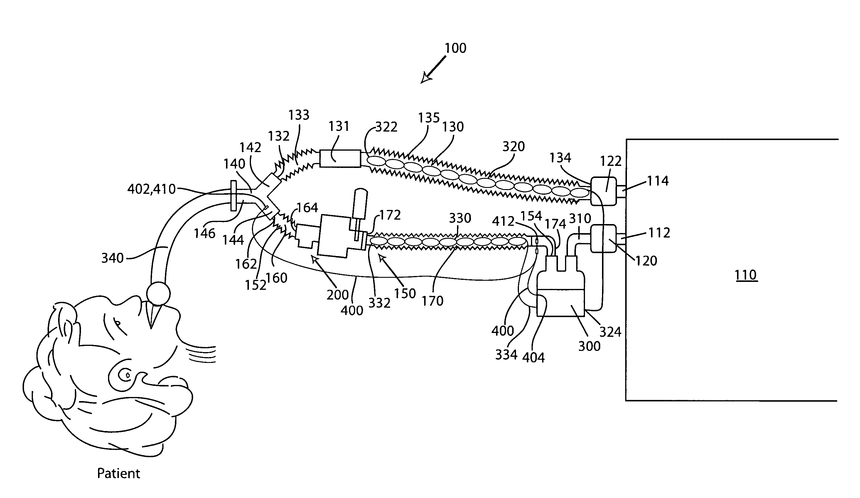
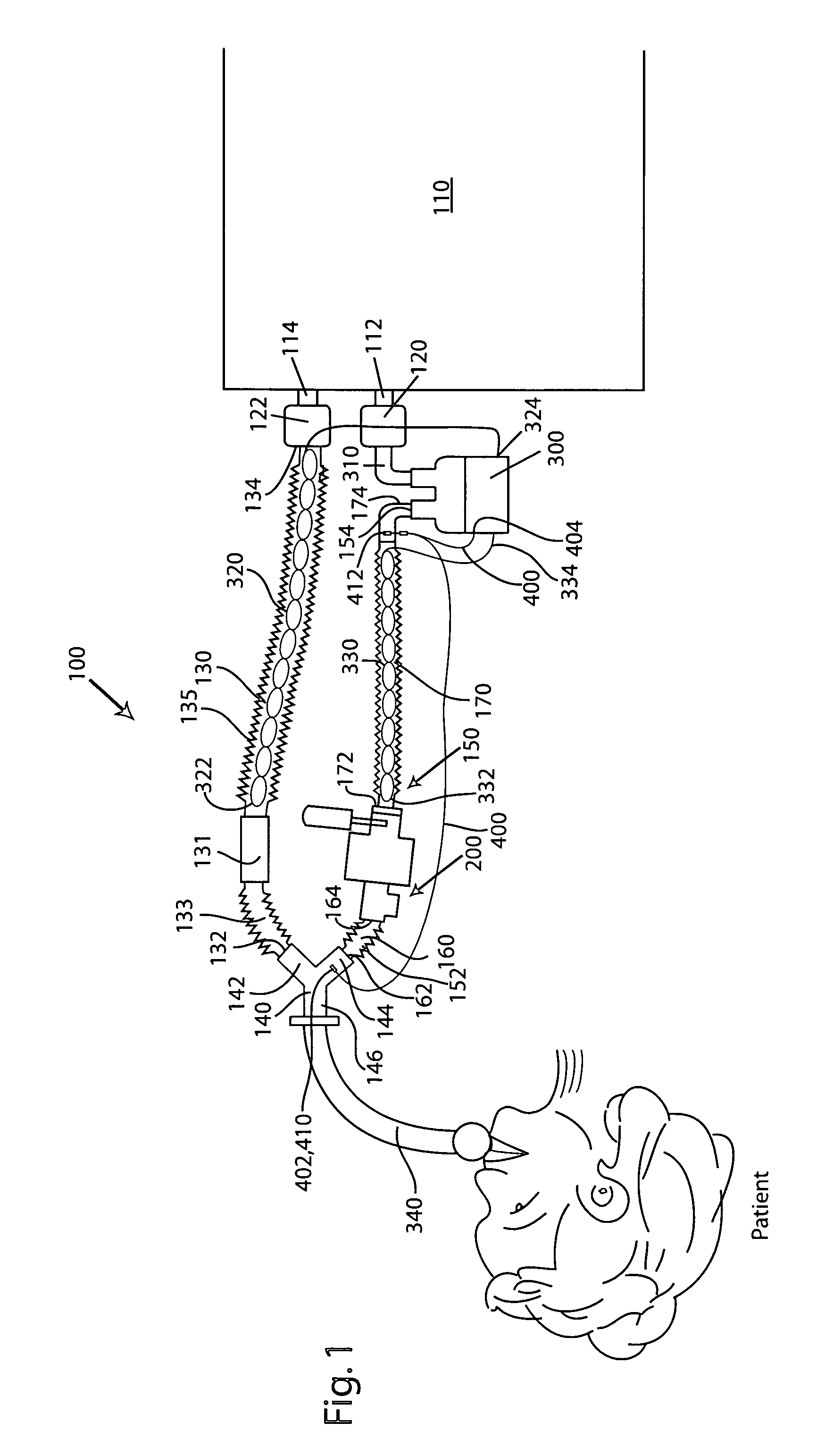
[0017]The inhalation conduit defines in part a holding chamber that has an adjustable interior volume due to the variable length of the conduit and therefore, the volume of the inhalation conduit can be advantageously varied depending upon a number of different parameters, such as the type of patient and more specifically, the weight of the patient. The volume can be varied by simply either expanding or contracting the inhalation conduit given its structure th...

Problems solved by technology

One of the problems associated with conventional ventilator design is the means by which medication is delivered into the ventilator system.
It will be appreciated that at this location, the MDI or nebulizer is very close to the endotracheal or tracheostomy tube and this is actually a disadvantage for several reasons described below.
While the Y-connector can include a port that serves as an attachment to the MDI, the Y-connector is not constructed for coupling to the nebulizer T connector.
Because an inside source of gas is used and the nebulizer is subject to the flow limitations of the ventilator itself, the dose of medication delivered to the patient over a fixed time is low.
In other words, it takes a significant time for the medication to be completely aerosolize...

Method used


Image

  • Patient interface assemblies for use in ventilator systems to deliver medication to a patient
  • Patient interface assemblies for use in ventilator systems to deliver medication to a patient
  • Patient interface assemblies for use in ventilator systems to deliver medication to a patient

Examples


first embodiment

[0058]A third leg 526 of the Y-connector 520 is attached to one end of a heat moisture exchanger (HME) 600 that is used instead of a humidifier unit for heating and adding moisture to the compressed air. The HME 600 is available from any number of different commercial suppliers and consists of a unit that includes a heat and moisture exchanger filter for use with mechanical ventilators to provide heat and humidity while retaining bacterial / viral contaminants. Unlike the humidifier unit 200 that is placed only in the inhalation tube of the patient circuit in the first embodiment, the HME 600 is in fluid communication with both air that is inhaled by the patient as well as air that is exhaled by the patient.

[0059]The system 500 includes a second Y-connector 540 that includes first, second and third legs 542, 544, 546, respectively, with the third leg 546 being attached to the other end of the HME 600. A third Y-connector 550 is provided and includes first, second, and third legs 552, ...

third embodiment

[0067]Now referring to FIG. 7, a ventilator system 700 is illustrated. The system 700 is very similar to the system 500; however, some of the conduits have been integrated with one another so as to share a common wall. In order, some of the conduits have been merged from a pair of conduit structures into a single conduit structure. For example, the first inhalation tube 510 and the first exhalation tube 530 can be merged together and share a common wall. Thus, when it is desired to change the distance from the HME 600 to the ventilator device 110, only a single action due to the combined nature of the two conduits 510, 530. In the previous embodiment, each of the conduits 510, 530 required its own adjustment and manipulation in order to change the length thereof.

[0068]In addition, a portion of the second inhalation conduit 560 and the second exhalation conduit 570 is likewise combined into a single integrated conduit structure. For example and as shown, the second inhalation condui...


PUM


Abstract

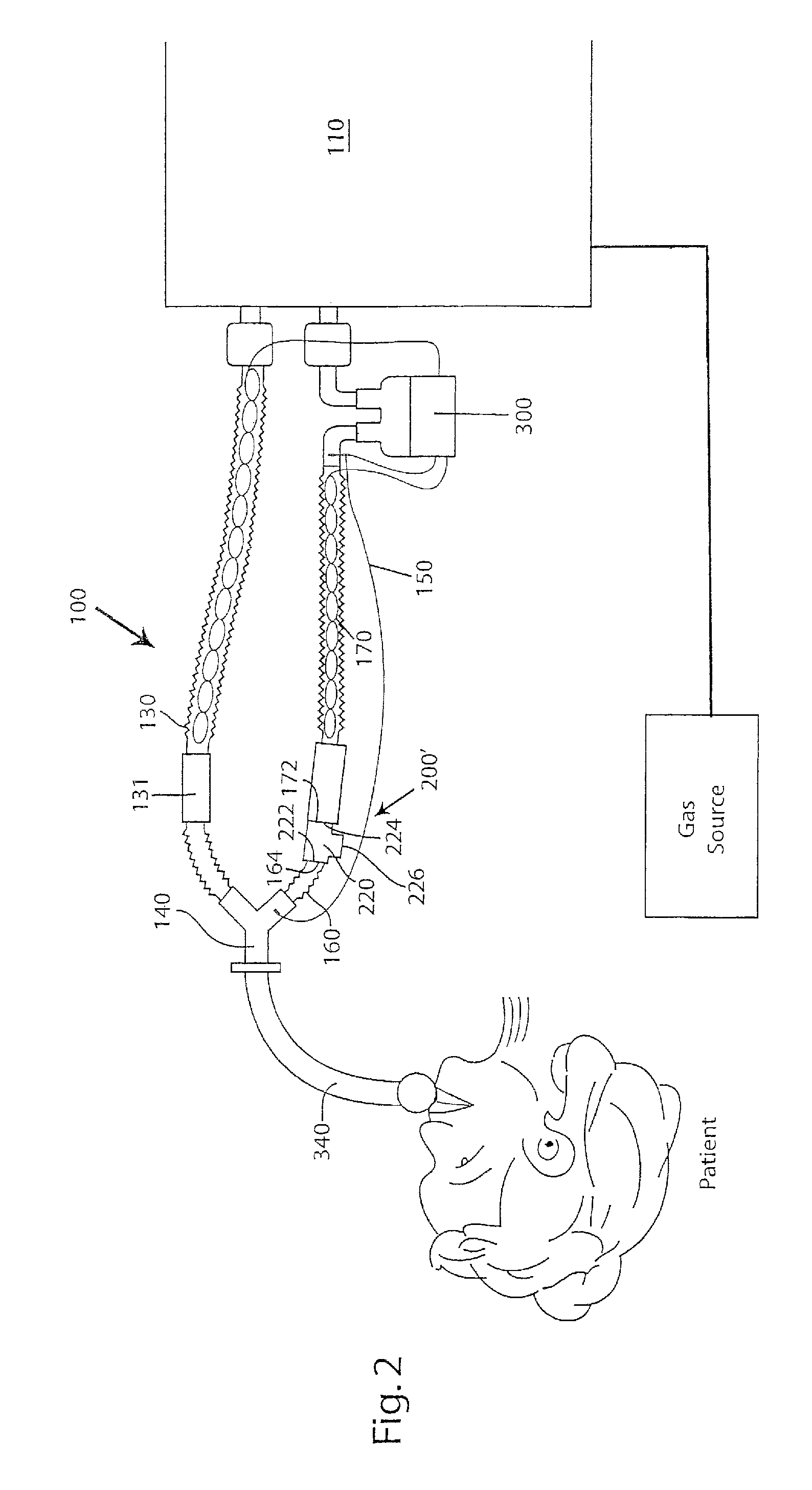
According to one aspect of the present invention, a ventilator system includes (a) a ventilator device having an inhalation port and exhalation port; (b) a patient conduit for delivering to and removing gas from the patient; (c) an exhalation conduit fluidly connected to the exhalation port and the patient conduit; (d) an inhalation conduit fluidly connected to the inhalation port and the patient conduit; and (e) a device for generating aerosolized medication, the device being fluidly connected to the inhalation conduit so that the aerosolized medication is delivered to the patient as the patient inhales. According to the present invention, at least the inhalation conduit has a variable length to position the device for generating aerosolized medication a predetermined distance from the patient conduit.

Description

CROSS-REFERENCE TO RELATED APPLICATION[0001]The present application claims the benefit of U.S. patent application Ser. No. 60 / 684,142, filed May 23, 2005, which is hereby expressly incorporated by reference in its entirety.TECHNICAL FIELD[0002]The present invention relates to inhalation equipment and more particularly, relates to a ventilator system that integrally incorporates a means for generating aerosolized medication into the inhalation flow path and also provides means for changing the location of the means for generating aerosolized medication relative to the patient in view of certain parameters, such as patient body weight, etc.BACKGROUND[0003]A ventilator is an automatic mechanical device designed to provide all or part of the work the body must produce to move gas into and out of the lungs. The act of moving air into and out of the lungs is called breathing, or, more formally, is called ventilation. During breathing, a volume of air is inhaled through the airways (mouth ...

Claims


Application Information

Patent Timeline
IPC IPC(8): A61M16/00A62B7/00A61M15/00F23D11/00
CPCA61M16/08A61M16/1095A61M16/1075A61M16/16A61M16/0833A61M15/009A61M16/04A61M16/1045A61M16/1055A61M2205/3368A61M16/106
Inventor DHUPER, SUNIL KUMARD'ALO, HERBERT FRED
Owner AEON RES & TECH INC
Why Eureka
Try Eureka