Enhanced implantable helical antenna system and method

Active Publication Date: 2011-01-18
PACESETTER INC
View PDF3 Cites 12 Cited by
  • Summary
  • Abstract
  • Description
  • Claims
  • Application Information

AI Technical Summary

Problems solved by technology

For instance, conventional antennas are found in enclosures, such as for heart pace makers, that require substantial room, which may be overly restrictive for other applications, such as vascular implantation.

Method used


Image

  • Enhanced implantable helical antenna system and method
  • Enhanced implantable helical antenna system and method
  • Enhanced implantable helical antenna system and method

Examples


Embodiment Construction

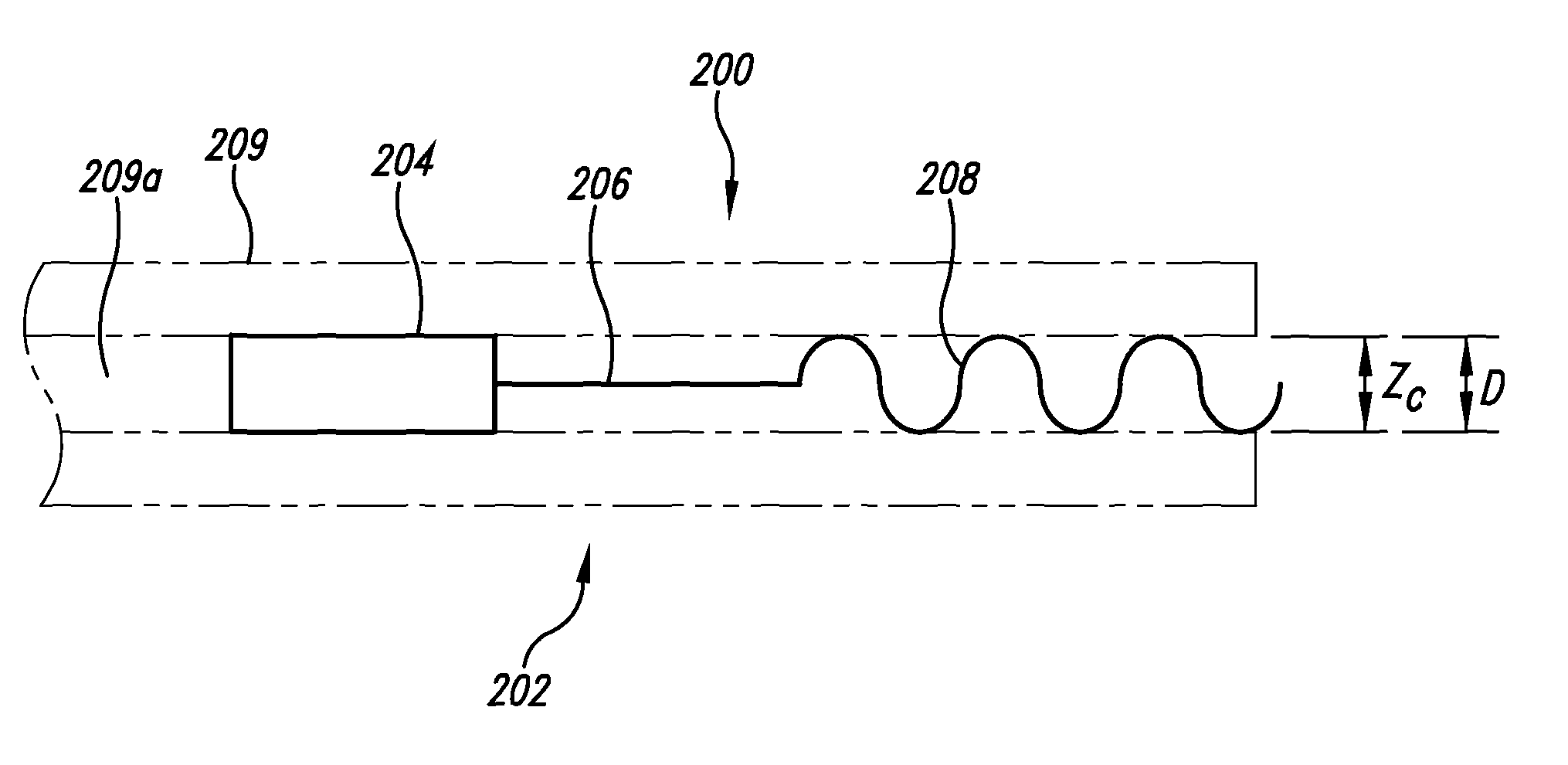
[0030]As discussed herein, implementations of an enhanced implantable system and method include use of one or more pseudoelastic and / or superelastic materials (referred to herein as “p / s elastic”) such as p / s elastic metal alloys, such as Nitinol, and / or p / s elastic polymers to provide at least a portion of the associated support structure for the implantable antenna. In implementations, the support structure has the general shape of the associated antenna either by one or more portions as integrated support structures being directly incorporated into the antenna structure typically as a tubular support structure and / or portions serving as a backbone support structure with a shape similar to the supported antenna components such as including inductive (H-field) and E-field antenna implementations discussed herein.

[0031]Use of p / s elastic material in the antenna support structure provides greater implantation adaptability and accommodation for the enhanced implantable antenna compare...


PUM


Abstract

As described herein vascular anchoring systems are used to position an implant in a vascular area such as a bifurcated vasculature with relatively high fluid flow, for instance, in an area of a pulmonary artery with associated left and right pulmonary arteries. Implementations include an anchoring trunk member having a first anchoring trunk section and a second anchoring trunk section. Further implementations include a first anchoring branch member extending from the anchoring trunk member. Still further implementations include a second anchoring branch member extending from the anchoring trunk member.

Description

BACKGROUND OF THE INVENTION[0001]1. Field of the Invention[0002]The present invention is generally related to antennas for implantable devices.[0003]2. Description of the Related Art[0004]Conventional implantable antennas can be constructed with a manner of accommodation with respect to incorporation into a body that is less than desirable. For instance, conventional antennas are found in enclosures, such as for heart pace makers, that require substantial room, which may be overly restrictive for other applications, such as vascular implantation.BRIEF DESCRIPTION OF THE SEVERAL VIEWS OF THE DRAWING(S)[0005]FIG. 1 is a sectional view of a first implementation of the enhanced implantable antenna system using a tubular support structure.[0006]FIG. 2 is a sectional view of a second implementation of the enhanced implantable antenna system using the tubular support structure.[0007]FIG. 3 is a sectional view of a third implementation of the enhanced implantable antenna system using the tu...

Claims


Application Information

Patent Timeline
Patent Type & Authority Patents(United States)
IPC IPC(8): H01Q1/36
CPCH01Q1/362H01Q7/00H01Q9/26A61N1/37229
Inventor KEILMAN, GEORGE W.JOHNSON, TIMOTHY
Owner PACESETTER INC
Why Eureka
Try Eureka