Method and system for synchronous high speed Ethernet GFP mapping over an optical transport network

a high-speed ethernet and optical transport technology, applied in the field of synchronous high-speed ethernet gfp mapping over an optical transport network, can solve problems such as network management complexity, potential traffic problems, and limitations

Active Publication Date: 2011-01-18
CIENA
View PDF10 Cites 20 Cited by
  • Summary
  • Abstract
  • Description
  • Claims
  • Application Information

AI Technical Summary

Problems solved by technology

Since the standard Optical Channel Transport Unit-2 (“OTU2”) signal normally runs at 10.709225 Gb / s, the over-clocked signal results in a further protocol on the OTN side to the standard one, requiring additional circuitry to implement and further complicating network management by creating potential traffic issues at OTU2 network interfaces between equipment providers.
As such, the over-clocked OTU2e approach can work in Synchronous Ethernet but has its limitations.
While G.8261 provides specifications for the timing requirements, it does not address how to actually implement these requirements.
Thus, this approach will not work for synchronous Ethernet.
Because the timing sources in the above prior art method are not synchronized, this method is unsuitable for use with Synchronous Ethernet networks.

Method used


Image

  • Method and system for synchronous high speed Ethernet GFP mapping over an optical transport network
  • Method and system for synchronous high speed Ethernet GFP mapping over an optical transport network
  • Method and system for synchronous high speed Ethernet GFP mapping over an optical transport network

Examples


Embodiment Construction

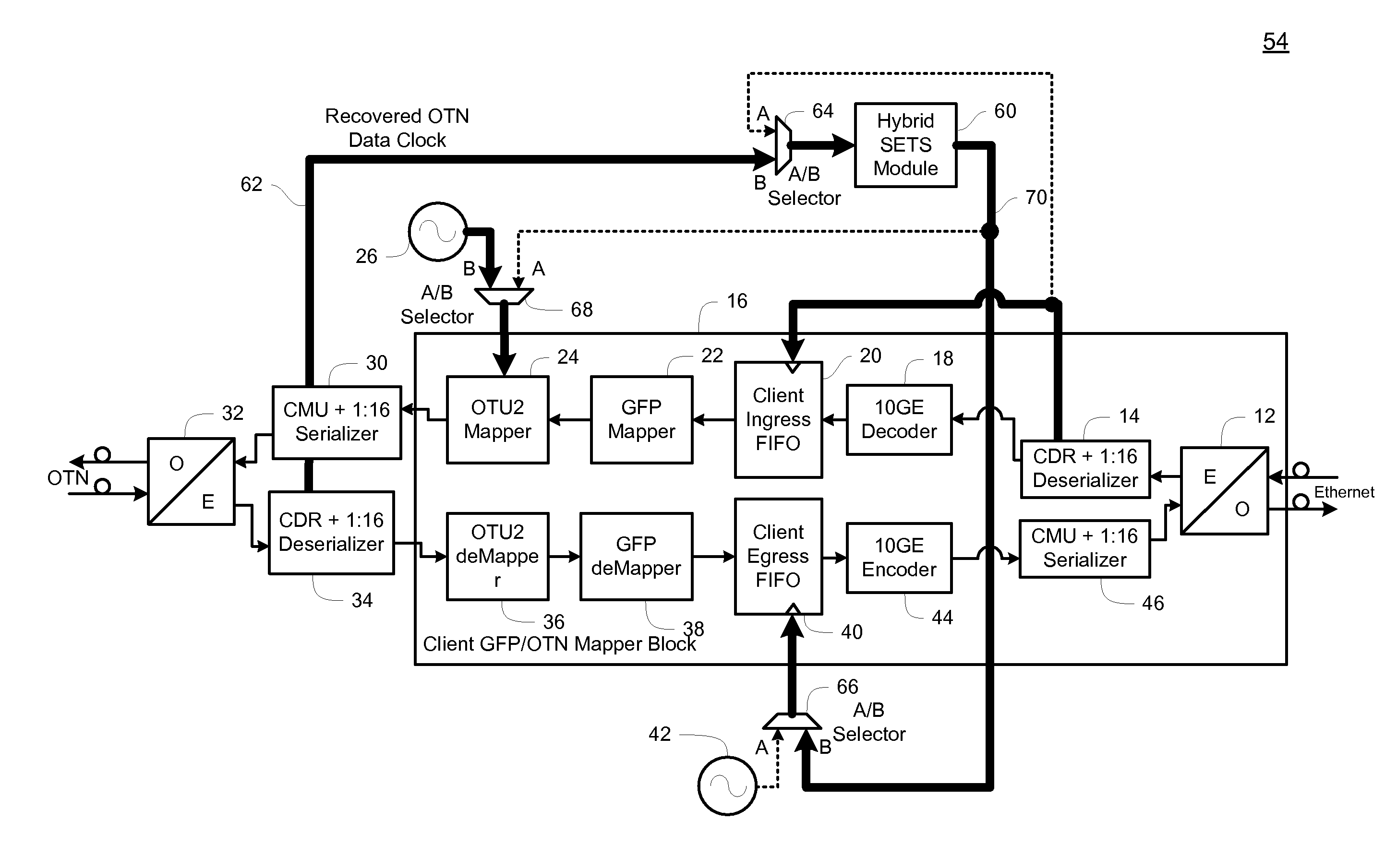
[0026]Before describing in detail exemplary embodiments that are in accordance with the present invention, it should be observed that the embodiments reside primarily in combinations of apparatus components and processing steps related to implementing a system and method for distributing reference timing between an Ethernet switched network and an optical transport network while maintaining phase stability and frequency accuracy. Accordingly, the apparatus and method components have been represented where appropriate by conventional symbols in the drawings, showing only those specific details that are pertinent to understanding the embodiments of the present invention so as not to obscure the disclosure with details that will be readily apparent to those of ordinary skill in the art having the benefit of the description herein.

[0027]In this document, relational terms, such as “first” and “second,”“top” and “bottom,” and the like, may be used solely to distinguish one entity or eleme...


PUM


Abstract

An interworking device, method and system distribute reference timing between at least two communication networks. The interworking device includes a first communication interface operable to communicate with a first communication network operating using a first communication protocol and a second communication interface operable to communicate with a second communication network operating using a second communication protocol. The interworking device also includes a client generic framing procedure / optical transport network (“GFP / OTN”) mapping block in communication with the first communication interface and the second communication interface. The client GFP / OTN mapping block recovers a first reference timing signal from data received from the first communication network. At least one hybrid synchronous equipment timing source transforms the first reference timing signal into a second reference timing signal that is phase and frequency locked to the first reference timing signal, and supplies the second reference timing signal to the client GFP / OTN mapping block to clock the second communication network.

Description

CROSS-REFERENCE TO RELATED APPLICATION[0001]n / aSTATEMENT REGARDING FEDERALLY SPONSORED RESEARCH OR DEVELOPMENT[0002]n / aFIELD OF THE INVENTION[0003]The present invention relates generally to a method and system for distributing timing within packet based networks and more specifically to a method and system for distributing reference timing between an Ethernet switched network and an optical transport network while maintaining phase stability and frequency accuracy.BACKGROUND OF THE INVENTION[0004]Until recently, packet networks, such as Ethernet, have been inherently asynchronous. However, as the data communication world moves toward an all Internet Protocol (“IP”) core and Ethernet based edge network, there is a need to provide synchronization to transform information carried on packet based networks for transport on long distance data communication networks. In other words, mapping of Ethernet into a Time-Division-Multiplexed-based (“TDM”) network such as Synchronous Optical Netwo...

Claims


Application Information

Patent Timeline
Patent Type & Authority Patents(United States)
IPC IPC(8): H04J3/06
CPCH04J3/1658H04L12/2885H04J3/0673H04J3/0688
Inventor FRLAN, EDWARDWATFORD, MICHAEL
Owner CIENA
Why Eureka
Try Eureka