Height adjustment device for motor vehicles

a technology for height adjustment and motor vehicles, applied in transportation and packaging, loading/unloading vehicle arrangment, transportation items, etc., can solve the problem of high space requirement, and achieve the effect of reducing the space required for the height adjustment device and larger gearing coverag

Inactive Publication Date: 2011-01-25
AUDI AG
View PDF12 Cites 10 Cited by
  • Summary
  • Abstract
  • Description
  • Claims
  • Application Information

AI Technical Summary

Benefits of technology

[0006]According to the invention, the gear speed connected between the drive motor and the control sleeve is not located outside of the control sleeve, but rather inside it. In this manner, the space required for the height adjustment device is reduced, particularly in the radial direction. In this manner, a drive connection may be made in an advantageous fashion between the gear speed and the control sleeve via an internal gearing. In comparison to an exterior gearing, an internal gearing of this type has a considerably larger gearing coverage, which is favorable in view of stability and noise emission.
[0007]Preferably, the gear speed may be a spur gear speed that may be produced in a simple fashion and requires little installation space inside the control sleeve, having gear wheels with an external tooth system. In order to further reduce the space requirements, the adjuster for the drive motor may be arranged in the remaining free space inside the control sleeve.
[0008]Advantageously, a drive pinion of the drive motor, preferably an electric motor, may be positioned inside the control sleeve and directly or indirectly cooperate with an internal gear set of the control sleeve. Here, the control sleeve may be part of a ball screw whose ball nut is arranged radially outside the control sleeve and inside the support spring. Thus, it is possible for the height adjustment device to also be embodied in a particularly short fashion, such that it may even optionally be retrofitted. By means of the radially interior actuator (drive pinion, internal gearing of the control sleeve), the control sleeve and therefore the ball nut may have a greater diameter inside the support spring such lower actuating forces are necessary and the robustness of the ball screw is increased.
[0010]Furthermore, it is advantageous for the ball nut to be guided in a positive fashion onto a section of the guide sleeve via a ring flange extending radially inwards in the circumferential direction. This may be accomplished, for example, by a serration between the section of the guide sleeve and the ring flange.
[0011]Moreover, it is possible for the drive pinion of the electric motor to be driven in an advantageous fashion directly by way of an intermediate gear wheel on the internal gearing of the control sleeve. In this manner, it is possible for the gear transmission ratio between the electric motor and the ball screw drive as well as for the spatial position of the electric motor to be optimally adapted to the structural conditions.
[0016]Moreover, it is possible for one elastic rubber dust boot each to be provided between the base plate of the housing and the adjustable spring plate as well as between a lower radial flange of the guide sleeve and the rotationally symmetric outer circumference of the ball nut, which would protect the mechanically movable parts of the height adjustment device from moisture and soiling.

Problems solved by technology

However, the gear connection between the drive motor and the control sleeve is realized such that it has a high space requirement.

Method used


Image

  • Height adjustment device for motor vehicles
  • Height adjustment device for motor vehicles
  • Height adjustment device for motor vehicles

Examples


Embodiment Construction

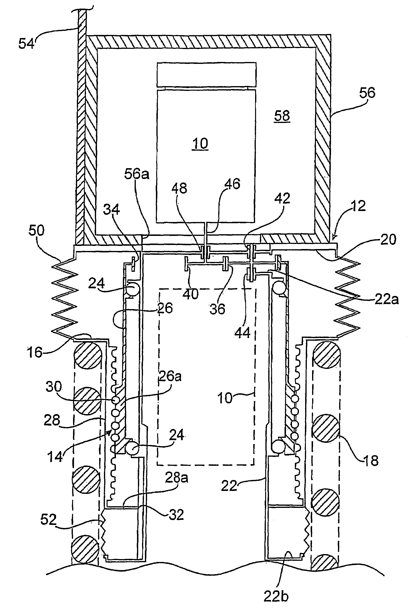
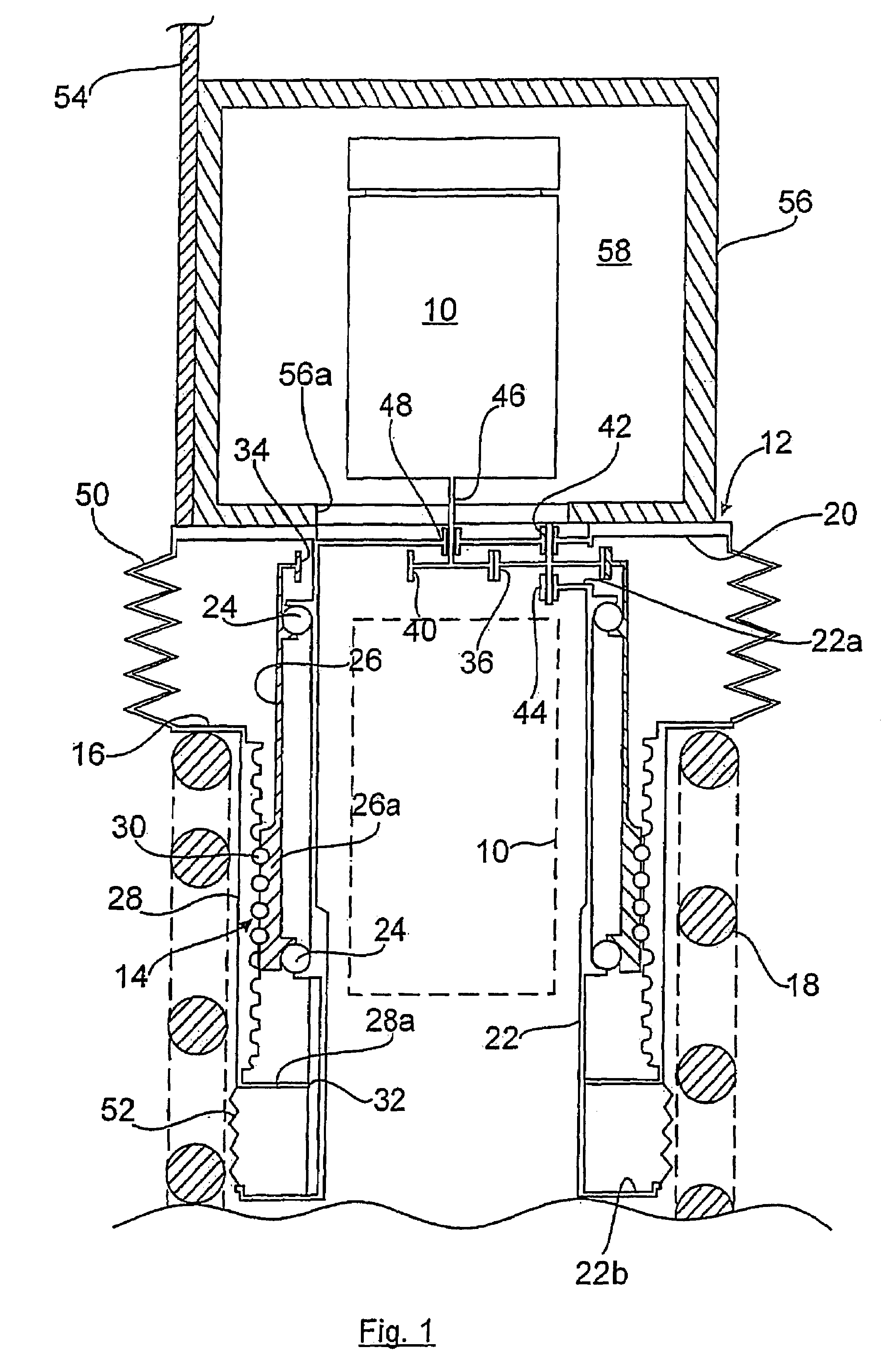
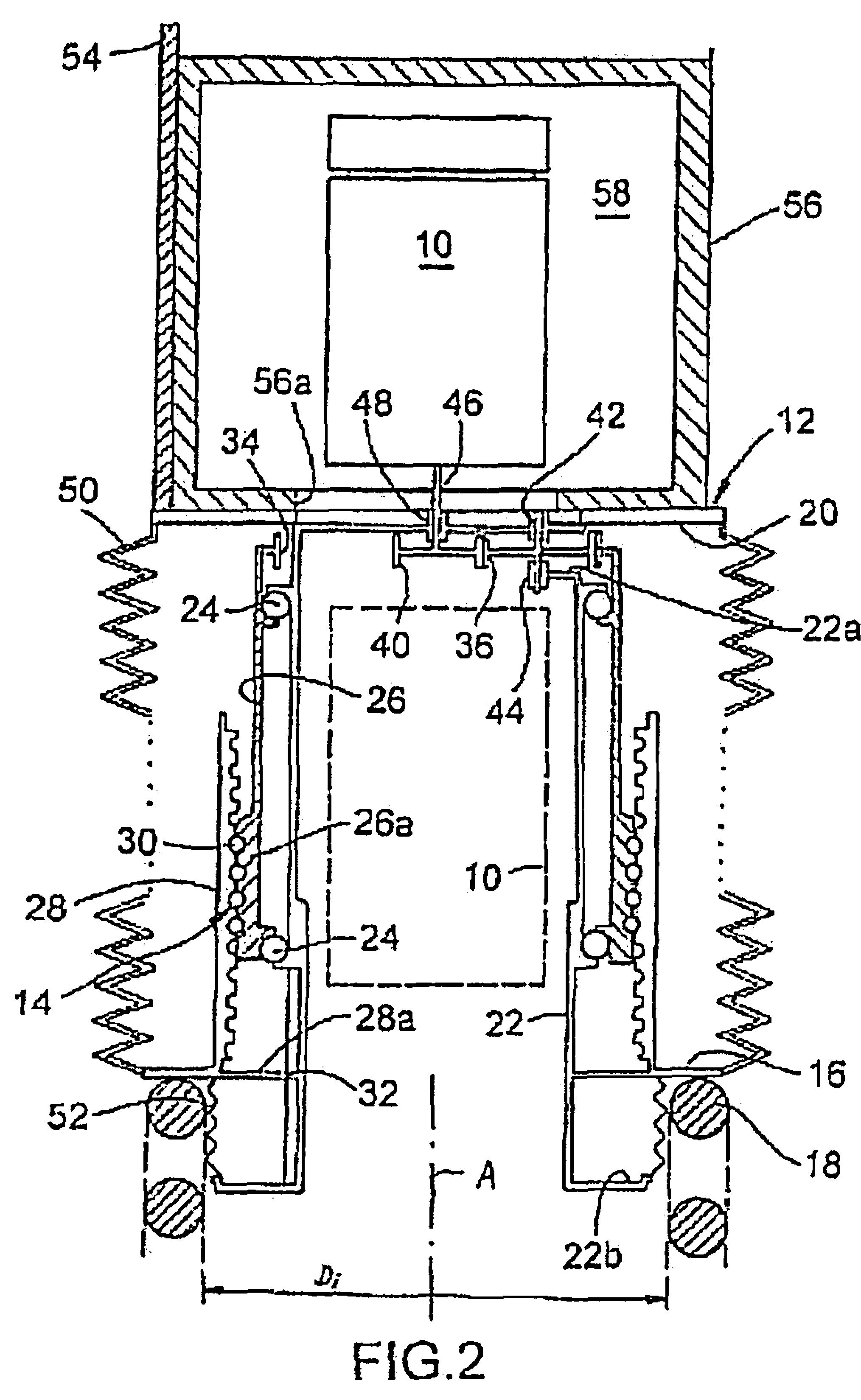
[0021]The height adjustment device for setting various level positions of the motor vehicle on a rear wheel suspension assembly is essentially composed of an electric motor 10, a housing 12, and a ball screw 14 on which an annular spring plate 16 is arranged as the assembly-side support for a support spring 18 (helical compression spring).

[0022]The support spring 18 is supported on the other side by a transverse control arm of the wheel suspension assembly, which is not shown and to which a telescopic shock absorber adjacent to the support spring 18 may optionally also be connected. The support may also occur directly on the wheel bearing.

[0023]The housing 12 of the height adjustment device is formed from an upper, disc-shaped base plate 20 and a guide sleeve 22 formed thereon that projects downwards.

[0024]The radially interior control sleeve 26 of the ball screw 14 is mounted on the guide sleeve 22 in a rotational fashion on via two roller bearings 24 or tapered roller bearings loc...


PUM


Abstract

The invention relates to a height adjustment device for motor vehicles that is arranged between a height-adjustable spring plate of a support spring of a wheel suspension assembly and the vehicle body and in which a drive motor cooperates via a shifted gear with a control sleeve that is mounted in a rotational fashion to adjust the height of the spring plate. According to the invention, the shifted gear connected between the drive motor and the control sleeve is arranged inside the control sleeve.

Description

CROSS-REFERENCE TO RELATED APPLICATIONS[0001]This application claims priority from German Application No. 102007012202.2 filed Mar. 4, 2007, hereby incorporated by reference in its entirety.[0002]The invention relates to a height adjustment device for motor vehicles.BACKGROUND OF THE INVENTION[0003]A height adjustment device of the generic type is known, for example, from DE 195 10 032 C2. In this device, a telescopic shock absorber, a helical support spring and a threaded drive with a control sleeve, a nut, and rolling elements inserted therebetween are combined into one unit. Here, the upper end of the support spring is located below the threaded drive, causing the unit to have a relatively large overall length.[0004]The control sleeve of the height adjustment device described above is rotationally actuated by means of an external drive motor. However, the gear connection between the drive motor and the control sleeve is realized such that it has a high space requirement. Thus, th...

Claims


Application Information

Patent Timeline
Patent Type & Authority Patents(United States)
IPC IPC(8): B60R17/00
CPCB60G17/021B60G2204/419B60G2204/4308
Inventor MICHEL, WILFRIED
Owner AUDI AG
Why Eureka
Try Eureka