Vehicle seat with a deformable backrest

Active Publication Date: 2011-01-25
GRAMMER AG
View PDF39 Cites 51 Cited by
  • Summary
  • Abstract
  • Description
  • Claims
  • Application Information

AI Technical Summary

Benefits of technology

[0010]The pivot axle can be displaced together with the seat part in the forward and backward direction and a pivotable section of the rocker-like element is attached to the base frame in a backrest region of the base frame, preferably at a fixable distance therefrom. In this way, a forward movement of the seat part automatically sets a reduced lordosis position of the backrest in the lumbar spine region, which in the extreme case may even lead to a kyphosis-type deformation of the backrest in the lumbar spine region. This leads to a more comfortable seating position for the person using the vehicle seat, particularly when, together with the forward movement of the seat part, the latter is at the same time moved upwards in the region towards the front of the vehicle, by means of a sliding bearing region which is angled with respect to the seat part surface, so as to give rise to a height adjustment of the seat part in the region towards the front of the vehicle during a displacement of the seat part in the forward direction. To this end, rail elements fitted to the underside of the seat part can roll on roller-like elements with respect to the base frame.
[0013]Advantageously, the base frame can be pivoted in the forward and backward direction in the region of the backrest so as to carry out the pivoting movement about an axle which extends horizontally. As a result, this backrest base frame can be inclined backwards regardless of whether the seat part is or is not displaced, in order thus to obtain in particular a backward-inclined shoulder region. In the process, the lumbar spine region changes such that the lordosis effect is slightly reduced.
[0014]Preferably, the rocker-like element is covered on its front side by a backrest pad which assumes a lordosis-type or kyphosis-type shape by pivoting an upper end of the rocker-like element. To this end, the rocker-like element is designed for example as a U-shaped rod 24 (FIG. 7) or as a plate-like element 28 (FIG. 10, as viewed facing the back side of the seat), wherein both the U-shaped rod and the plate-like element can additionally assist a lordosis or kyphosis effect such that it is designed to be curved or even S-shaped in the height direction of the backrest.
[0015]According to one preferred embodiment, the rocker-like element is connected at its upper end to essentially S-shaped rods 20 (FIGS. 8 and 9) which extend along the backrest. To this end, the upper end of the rocker-like element can be displaced along the rods 20 during a pivoting movement of the rocker-like element, as a result of which the rods 20, which are mounted such that they can rotate about a respective axle extending in the longitudinal direction of the backrest, can automatically change their position with respect to the front side of the backrest by displacing the upper end of the rocker-like element. In this way, a continuous change in the S-shape can be achieved at the same time as a sliding of the seat part in the forward or backward direction.

Problems solved by technology

Such a support member has an expensive and complicated structure in so far as it requires a device for securing the support member, sliding elements, and also a plurality of support arms which extend horizontally and are connected to one another.

Method used


Image

  • Vehicle seat with a deformable backrest
  • Vehicle seat with a deformable backrest
  • Vehicle seat with a deformable backrest

Examples


Embodiment Construction

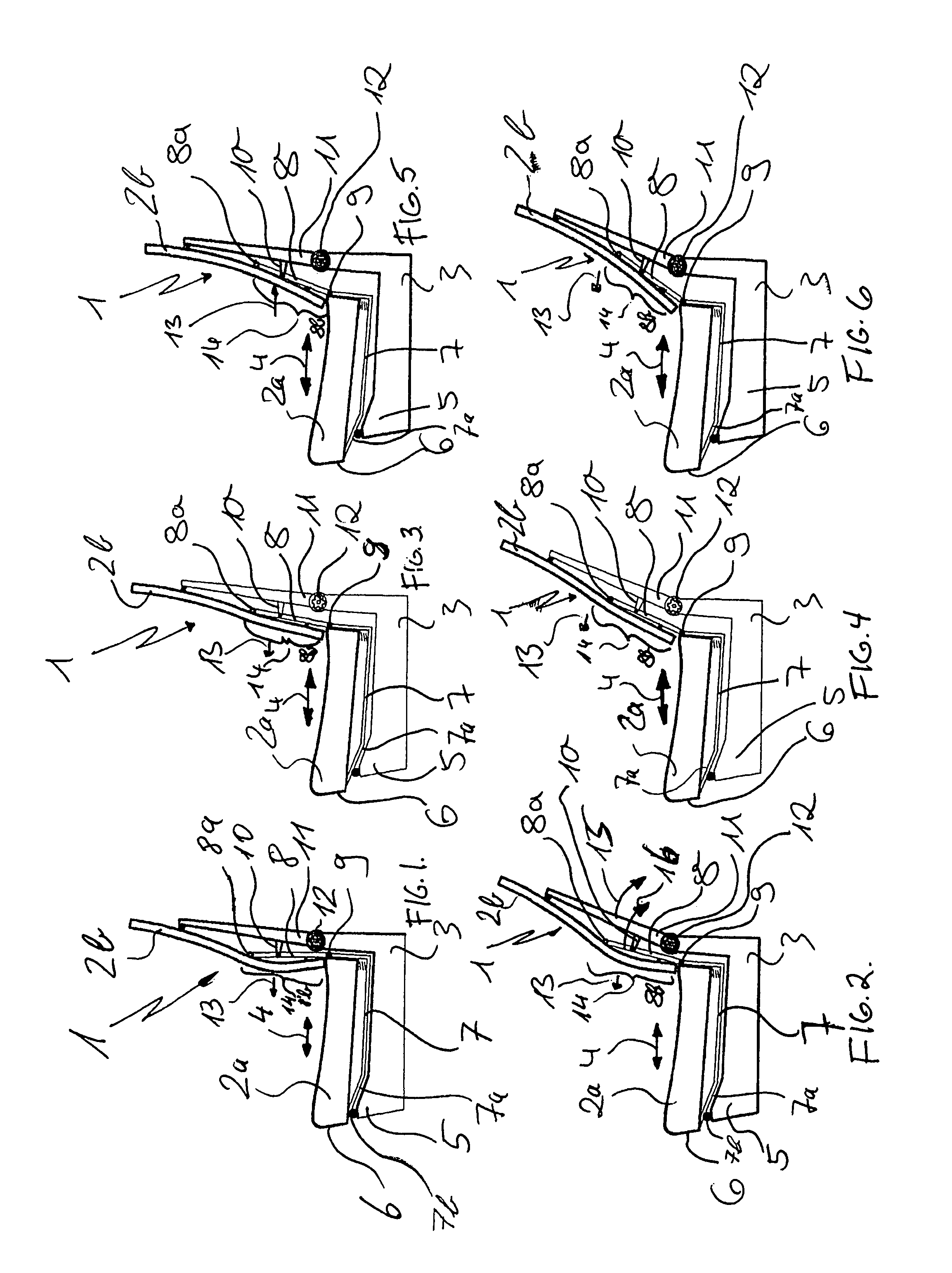
[0020]FIGS. 1 and 2 show the vehicle seat in the non-displaced position, but with a straight and inclined backrest. In FIGS. 3 and 4, the vehicle seat is shown with a displaced seat part and a non-inclined and inclined backrest. In FIGS. 5 and 6, the vehicle seat is shown with a seat part which has been displaced even further forwards and the non-inclined and inclined backrest.

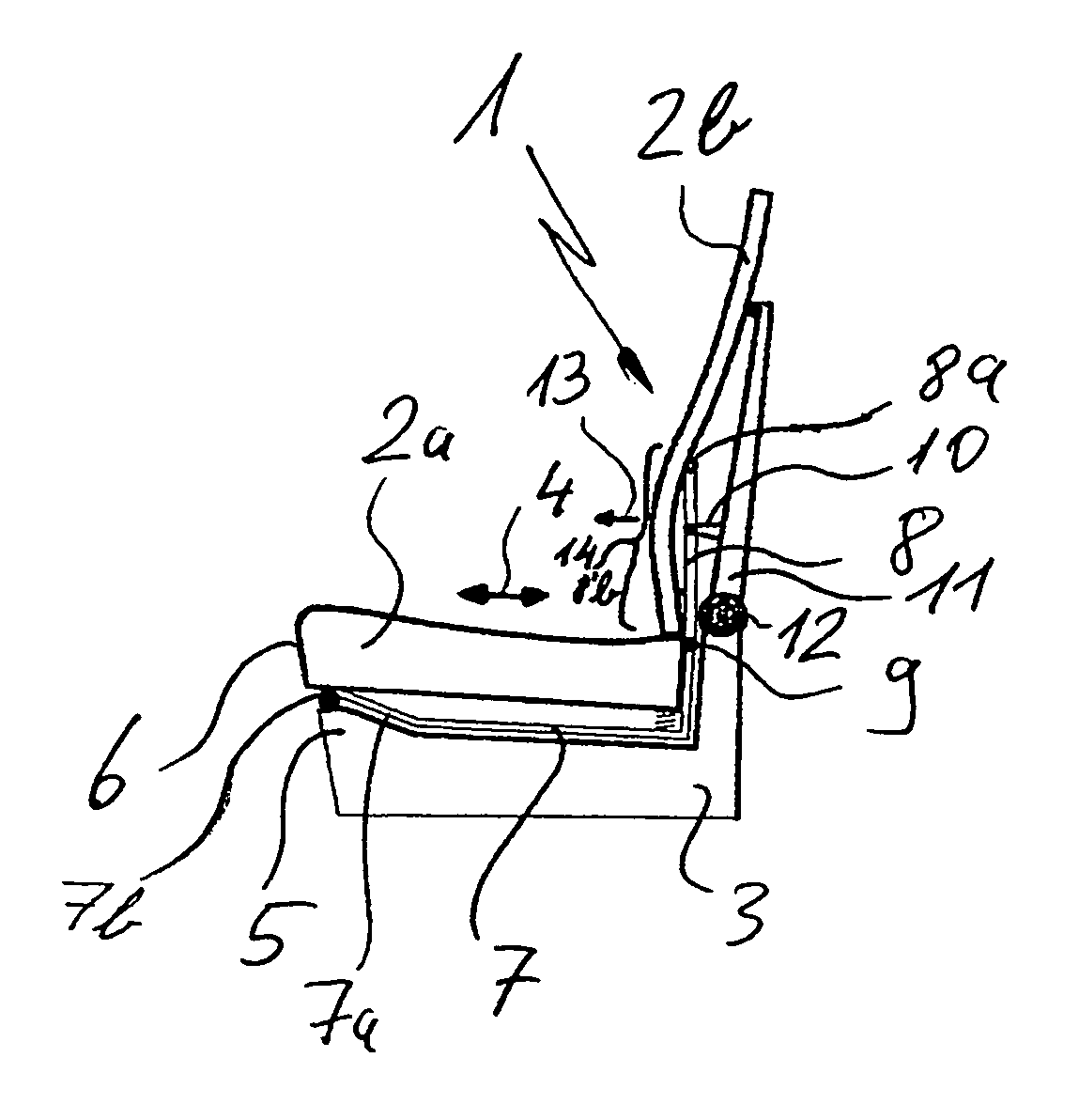
[0021]FIG. 1 shows a vehicle seat with a backrest 1 and a seat part 2a, wherein the backrest has a backrest pad 2b. Both the seat part 2a and also the backrest pad 2b are arranged in a base frame 3.

[0022]The seat part 2a can be displaced in the forward and backward direction 4 by means of a sliding bearing system 7, 7a.

[0023]During such a forward displacement movement, a region 6 of the seat part 2a towards the front of the vehicle is automatically lifted since a front region of the base frame 3 is designed to be raised. As a result, the sliding bearing section 7a, which is arranged at an angle with respect t...


PUM


Abstract

The invention relates to a vehicle seat with a backrest (1) and a seat part (2a), wherein the seat part (2a) can be displaced in the forward and backward direction (4) with respect to a base frame (3, 11) and the backrest (1) has a lumbar spine region (14) which can be deformed in the forward and backward direction (13), wherein a rocker-like element (8) is provided which is arranged in the lumbar spine region (14) such that it can pivot about a horizontally running pivot axle (9), said rocker-like element extending at least partially along the longitudinal direction of the backrest, wherein the pivot axle (9) can be displaced together with the seat part (2a) in the forward and backward direction (4) and a pivotable section (8b) of the rocker-like element (8) is attached to the base frame (3, 11) in a backrest region of the base frame (3, 11).

Description

PRIORITY CLAIM[0001]This application claims priority to German Application DE 10 2005 017 713.1 filed Apr. 15, 2005.BACKGROUND OF THE INVENTION[0002]EP 0 957 716 B1 discloses a vehicle seat with a backrest and a seat part, in which a lumbar support mechanism is installed in the backrest region, said lumbar support mechanism being composed of a flexible support member which is secured at its upper and lower ends and can be drawn together such that an arch forms for example in the lumbar spine region. As a result, a lumbar support is obtained which can be adjusted in the forward direction so as, by means of a convex deformation of the backrest in the lumbar spine region, to provide more or less support for the person depending on whether said person has a more or less pronounced hollow in the small of his back, in order to increase the seating comfort.[0003]The deformation of such lumbar spine supports is preset by the person, and remains as such until the person readjusts it for exam...

Claims


Application Information

Patent Timeline
IPC IPC(8): A47C7/46
CPCB60N2/2209B60N2/643B60N2/66
Inventor KOHL, JOSEFERKER, CHRISTIAN
Owner GRAMMER AG
Why Eureka
Try Eureka