Digital tool with a light display

a digital tool and light display technology, applied in the field of digital tools, can solve the problems of poor warning effect of sound signal, inability to observe the lighting state of the led directly, and etc., and achieve the effect of small light display area, poor directionality, and poor warning

Active Publication Date: 2011-01-25
ECLAT TORQ TECH
View PDF2 Cites 7 Cited by
  • Summary
  • Abstract
  • Description
  • Claims
  • Application Information

AI Technical Summary

Benefits of technology

[0010]Considering that the sound signal has a poor warning effect during the operation of a general digital tool, and the optical signal has the disadvantages of small light display area, poor directionality, the present invention provides a digital tool which has a light alternation display effect and large light display area.
[0011]The primary objective of the present invention is to provide a digital tool with a light display, which can produce an obvious light display effect to remind the user of the present operating state.

Problems solved by technology

However, as for the noisy working environment, the sound signal is frequently ignored or even not heard at all, so that using sound signal to warn the user is not effective, and using optical signal as warning signal will be more useful in various working environments.
Nevertheless, in such a torque tool, the light-emitting surface is small and the visible area is also small, so that once the user is located at a position opposite the LED to observe the LED, the lighting state of the LED cannot be observed directly.
However, the protruding transparent surface is possibly damaged since the torque tool is improperly placed or moved or trampled by the user.
Therefore, the above structure design is also not ideal.

Method used


Image

  • Digital tool with a light display
  • Digital tool with a light display
  • Digital tool with a light display

Examples


Embodiment Construction

[0026]The present invention will be clearer from the following description when viewed together with the accompanying drawings, which show, for purpose of illustrations only, the preferred embodiment in accordance with the present invention.

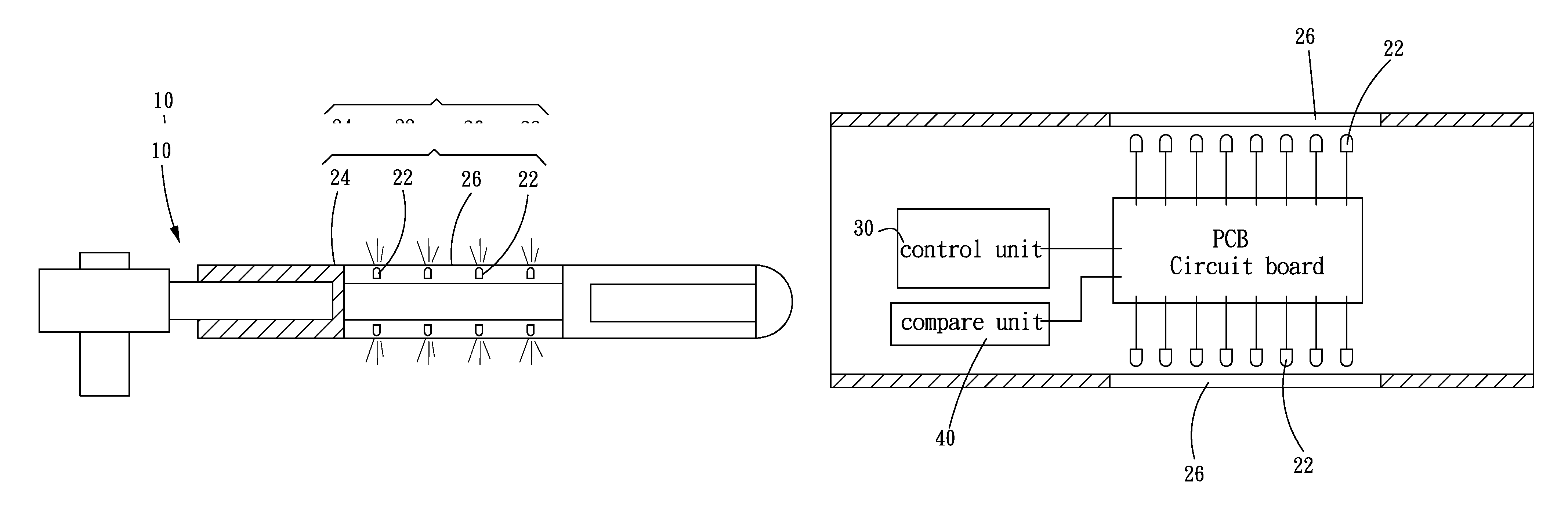
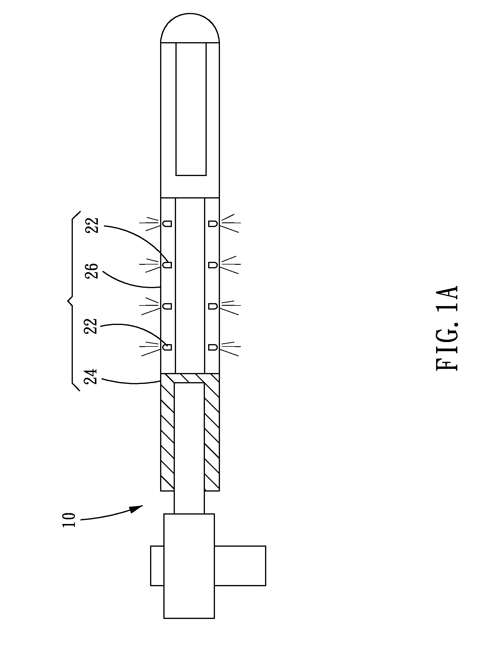
[0027]Referring to FIG. 1A, a digital tool with a light display in accordance with the present invention is used to produce an operation force and has a function of setting or being inherently set with a predetermined condition. The digital tool in accordance with the present invention comprises a tool body 10, and a light display assembly 20 assembled on the tool body 10. The light display assembly 20 is provided with four or more light-emitting elements 22, for example, the light-emitting diodes, and each of the light-emitting elements 22 is located opposite a light-transmitting element 24. Further speaking, the light-transmitting element 24 has a light-transmitting area 26 opposite the light-emitting elements 22.

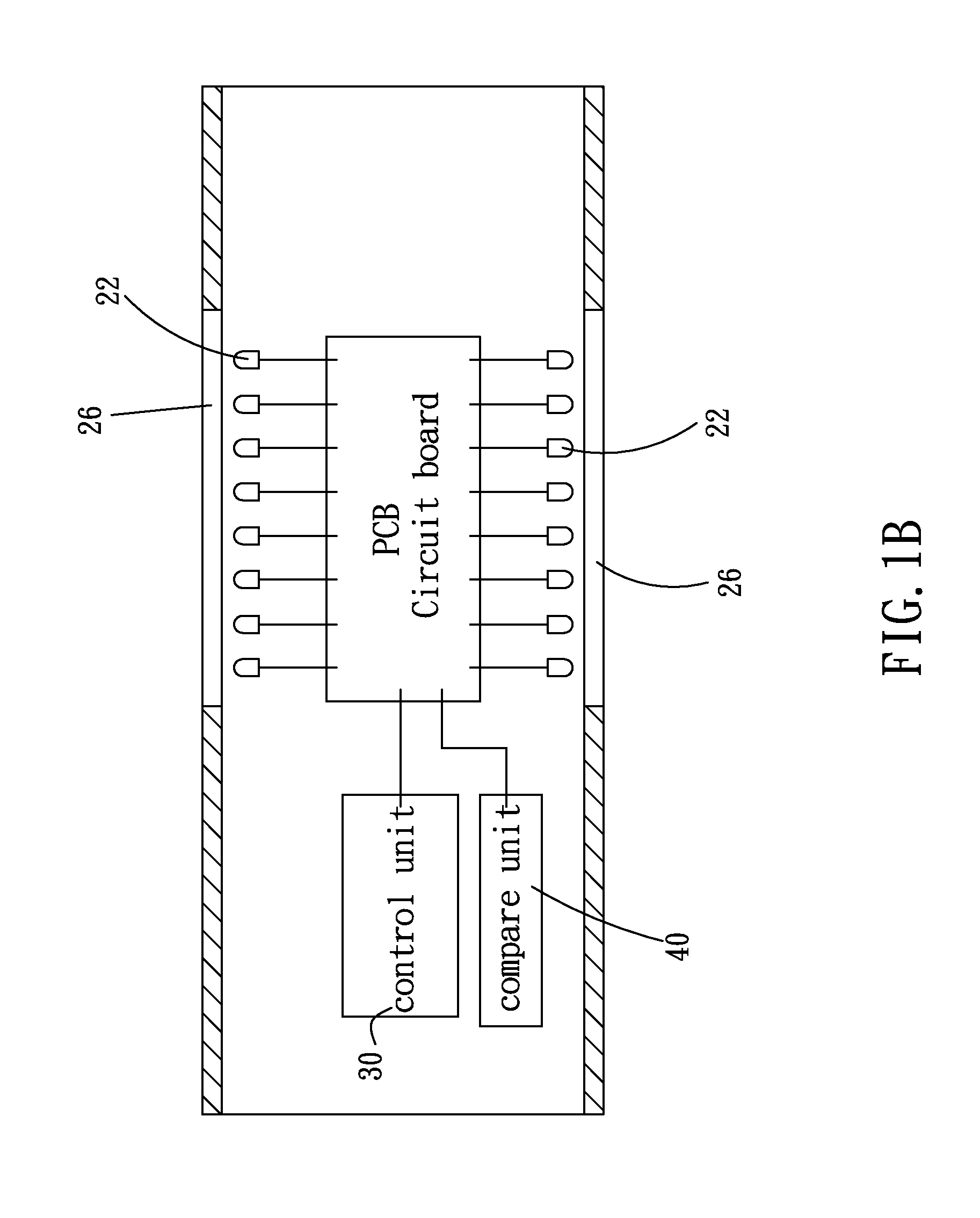
[0028]Referring to FIG. 1B, a c...


PUM


Abstract

A digital tool with a light display comprises at least one light display assembly. The light display assembly includes four or more light-emitting elements to cooperate with a light-transmitting element. The light display assembly can be the whole or a part of a handle sleeve. Therefore, by cooperating with a compare unit and a control unit, under the predetermined condition, the light-emitting elements can emit light through the light-emitting area synchronously or alternately.

Description

BACKGROUND OF THE INVENTION[0001]1. Field of the Invention[0002]The present invention relates to a digital tool, and more particularly to a digital tool with a light display, which can facilitate the user observing the light from the digital tool.[0003]2. Description of the Prior Art[0004]A common digital torque tool is a tool that itself can be provided to set a predetermined condition or a tool that has been inherently set with the predetermined condition before leaving the factory. When in use, once the operation torque satisfies the predetermined condition, the tool itself will emit a sound signal to warn the user, and meanwhile, the tool will be powered off to stop outputting torque.[0005]However, as for the noisy working environment, the sound signal is frequently ignored or even not heard at all, so that using sound signal to warn the user is not effective, and using optical signal as warning signal will be more useful in various working environments.[0006]Generally speaking,...

Claims


Application Information

Patent Timeline
Patent Type & Authority Patents(United States)
IPC IPC(8): B25B23/18
CPCB25B23/1422B25B23/1425B25G1/00Y10S362/80
Inventor LI, MING-HUA
Owner ECLAT TORQ TECH
Why Eureka
Try Eureka