Incontinence device

a technology of incontinence and incontinence, which is applied in the field of incontinence devices that can be vaginally inserted, can solve the problems of device discomfort, leakage and soiling of garments, and at best reliable non-invasive means, so as to prevent urine leakage, prevent leakage, and ensure the effect of safety

Inactive Publication Date: 2011-01-25
FRAZIER LATOYA NICOLE +1
View PDF19 Cites 33 Cited by
  • Summary
  • Abstract
  • Description
  • Claims
  • Application Information

AI Technical Summary

Benefits of technology

[0012]In use, the trough is fixed against the female so as to substantially encompass the female's labia area. The vaginal anchor means is at least partially inserted in the female's vagina, if desired. With the valve means in the closed position, the trough and the drainage conduit may collect urine from the urethra without leaking through the open top end of the trough, the material of the trough and the attachment apertures sealing the device against the female. The at least one side wall may further include a less flexible ring region for forming a seal against the female's labia area. As such, the female may use the device in either a prone or an upright position, and all the while the device is held firmly against the female to prevent urine leakage therearound. Optionally, a V-shaped clip, made of soft but resilient material, or other friction-based attachment means may be included for securing the trough to the female's clitoris, if desired. The V-shaped clip may assume an alternate shape for gripping the clitoris, such as U-shaped, or the like.
[0013]The present device is an incontinence device that is able to lie substantially flat between the woman and one or more garments, yet still maintain a suitable seal around the woman's urethra and prevent leaking when the woman is in either a prone or an upright position. The present invention is comfortable to wear, and allows the option of a removable vaginally-inserted anchoring means of various shapes, sizes, and orientations so as to allow for individual comfort preferences. The present device allows for use with a urine bag, if desired, secured around the user's leg, for example, or for direct discharge directly into a toilet, bed pan, or the like. The present invention provides a drainage conduit that is flexible and that has an easy-to-use valve means to selectively open or close the drainage conduit. The present device further provides for a variety of additional attachment means, including garments that are made to more firmly, yet comfortably, hold the device in place at attachment apertures. The present invention is further made from a comfortable, safe, flexible, either transparent or translucent material that is easily either washed or disposed of. The present device further provides additional attachment means that the user can use as necessary or as preferred. The present invention also includes a drainage tube that is adjustable, flexible so that it can be oriented either forward or rearward, and retractable and collapsible. Other features and advantages of the present invention will become apparent from the following more detailed description, taken in conjunction with the accompanying drawings, which illustrate, by way of example, the principles of the invention.

Problems solved by technology

Such prior art devices have the drawback that, even with the attachment means taught in each, relying on non-invasive means is at best sporadically reliable.
Frequently such devices become misaligned, resulting in leakage and soiling of garments.
Further, such devices are typically uncomfortable in that they are made from a material that is somewhat rigid and cannot be pressed substantially flat against the body between the user's garments.
Such a device requires the use of a vaginally-inserted portion, and thus there is no alternate attachment means for women who do not desire such insertion.

Method used


Image

  • Incontinence device
  • Incontinence device
  • Incontinence device

Examples


Embodiment Construction

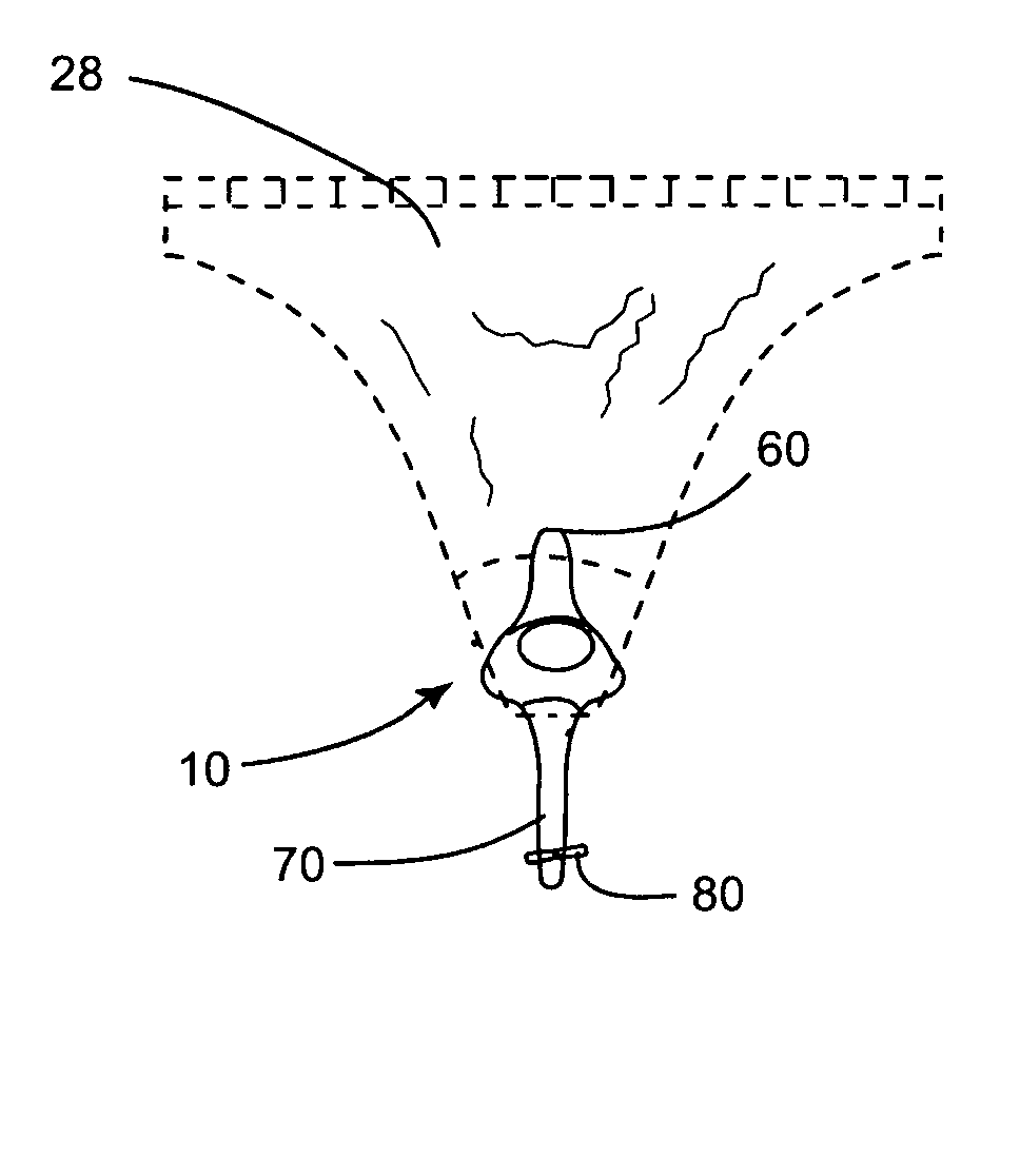
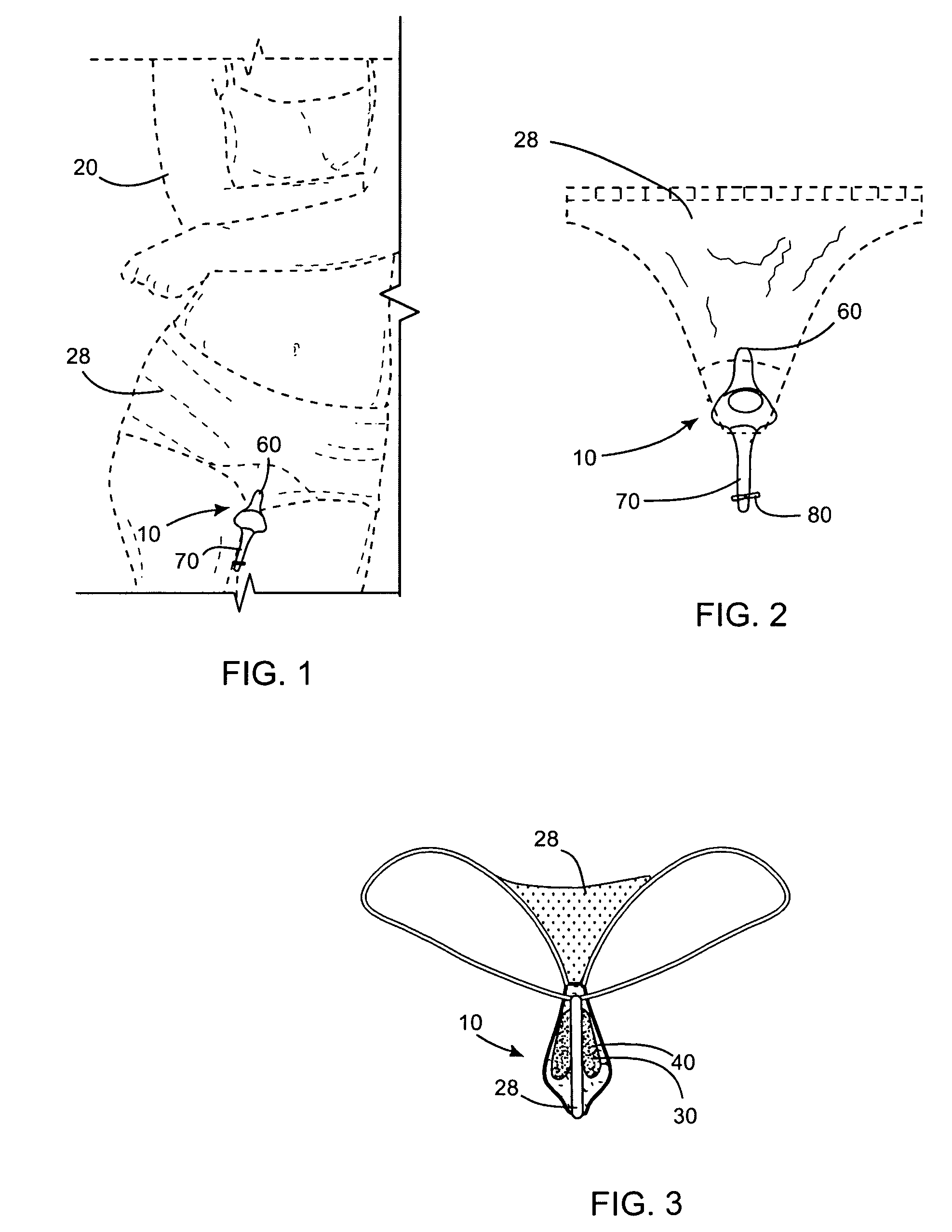
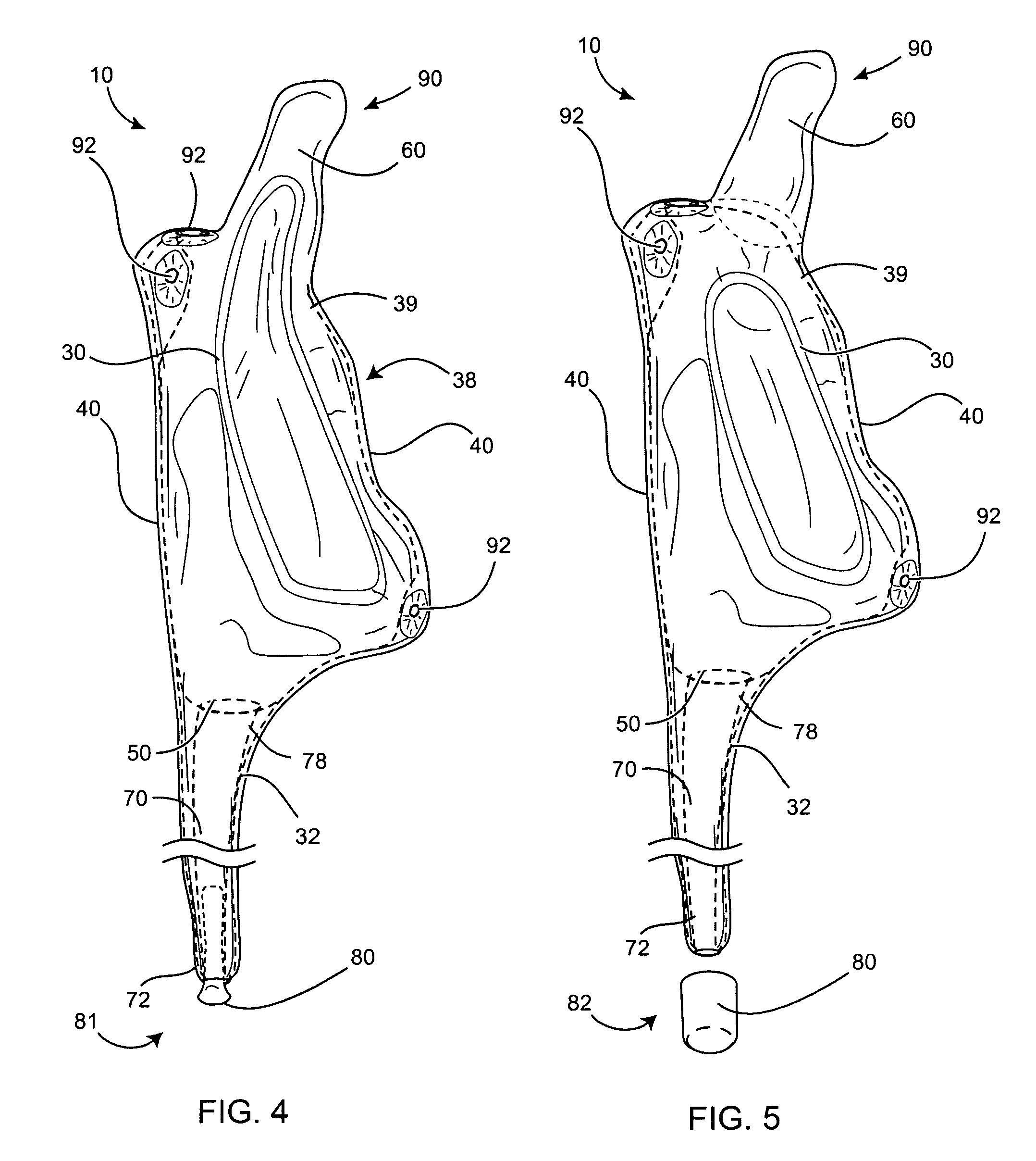
[0022]FIGS. 1, 2, 4, 5 and 6 illustrate an incontinence device 10 for wearing by a female 20 having a labia area 24, a urethra 25, bladder 27, pubic bone 23, a clitoris 22, and a vagina 26. A urine collection trough 30 has an elongated open top end 38 that is adapted to fit around the labia area 24 of the female 20, encompassing her urethra 25.

[0023]The trough 30 has at least one non-rigid side wall 40, preferably being made from a resilient silicone rubber, latex, vinyl, medical-grade rubber, or the like, and is made from a relatively thin opaque, transparent or translucent such resilient material so that the device will lie substantially flat against the female 20 when worn between the female 20 and an article of clothing 28. The trough 30 may be made in any color or transparency.

[0024]The trough 30 further includes a drainage aperture 50 in a lower portion 32 thereof, and a vaginal anchor means 60 at an upper portion 39 thereof. The vaginal anchor means 60 is preferably a resilie...


PUM


Abstract

An incontinence device for wearing by a female is disclosed. A urine collection trough has an elongated open top end that is adapted to fit around the labia area of the female, encompassing her urethra. The trough has at least one non-rigid side wall and includes a drainage aperture in a lower portion thereof and a vaginal anchor means at an upper portion thereof. The vaginal anchor means is preferably a resilient protruding member fixed to the upper portion of the side wall of the trough. A drainage conduit is fixed at an upper end thereof to the drainage aperture that has at a lower end a valve means having an open position and a closed position. Preferably, the at least one side wall includes at least one attachment aperture therethrough, such that the device may be fixed to articles of clothing with straps, buttons, or the like.

Description

CROSS-REFERENCE TO RELATED APPLICATIONS[0001]This application claims the benefit of U.S. Provisional Patent Application 60 / 932,787, filed on Jun. 4, 2007, and incorporated herein by reference.STATEMENT REGARDING FEDERALLY SPONSORED RESEARCH AND DEVELOPMENT[0002]Not Applicable.FIELD OF THE INVENTION[0003]This invention relates to incontinence devices, and more particularly to a vaginally insertable incontinence device.DISCUSSION OF RELATED ART[0004]Prior art incontinence devices for females typically include a cup-shaped receptacle for catching urine from the female and delivering it to a urine bag, or the like. Prior art device are typically held to the female with a variety of belts, straps, tight-fitting undergarments, adhesive strips, and the like, so as to be non-invasive. For example, the following prior art patents and patent applications teach such devices: U.S. Pat. Nos. 4,886,508 to Washington on Dec. 12, 1989; 4,904,248 to Vallancourt on Feb. 27, 1990; 5,053,027 to Manfred...

Claims


Application Information

Patent Timeline
Patent Type & Authority Patents(United States)
IPC IPC(8): A61F5/44A61M1/00
CPCA61F5/455
Inventor FRAZIER, LATOYA NICOLEFRAZIER, ANNA BLAKNEY
Owner FRAZIER LATOYA NICOLE
Why Eureka
Try Eureka