
Missile tracking with interceptor launch and control

a technology of missile tracking and launch control, applied in direction controllers, instruments, using reradiation, etc., to achieve the effect of estimating the signal-to-noise ratio

Inactive Publication Date: 2011-01-25
LOCKHEED MARTIN CORP
View PDF32 Cites 26 Cited by
  • Summary
  • Abstract
  • Description
  • Claims
  • Application Information

AI Technical Summary

Problems solved by technology

One of the problems with defense against missile attack is that the attacker can deploy a cloud of chaff and / or multiple decoy objects during missile flight to confound identification of the actual lethal warhead within the cloud.

Method used


Image

  • Missile tracking with interceptor launch and control
  • Missile tracking with interceptor launch and control
  • Missile tracking with interceptor launch and control

Examples


Embodiment Construction

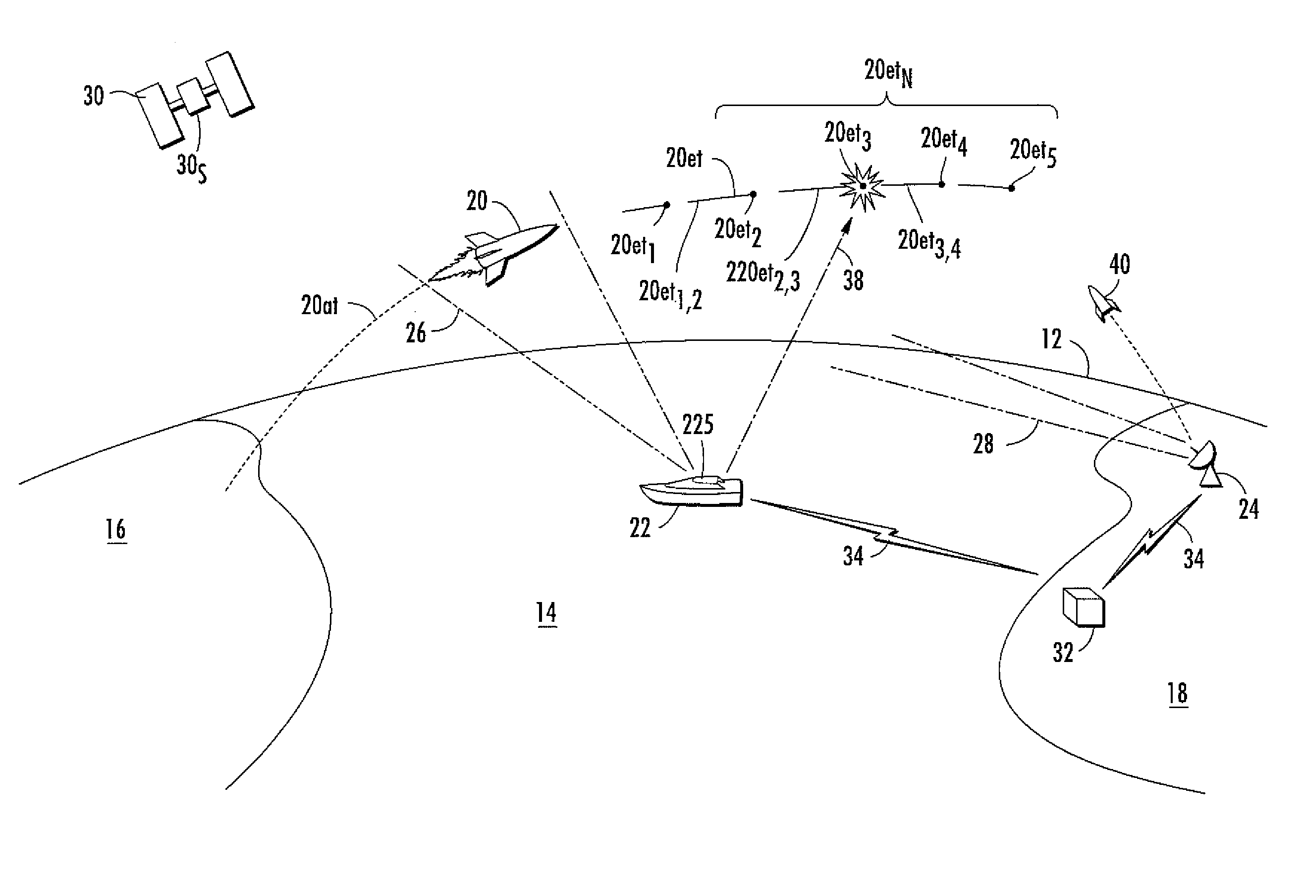
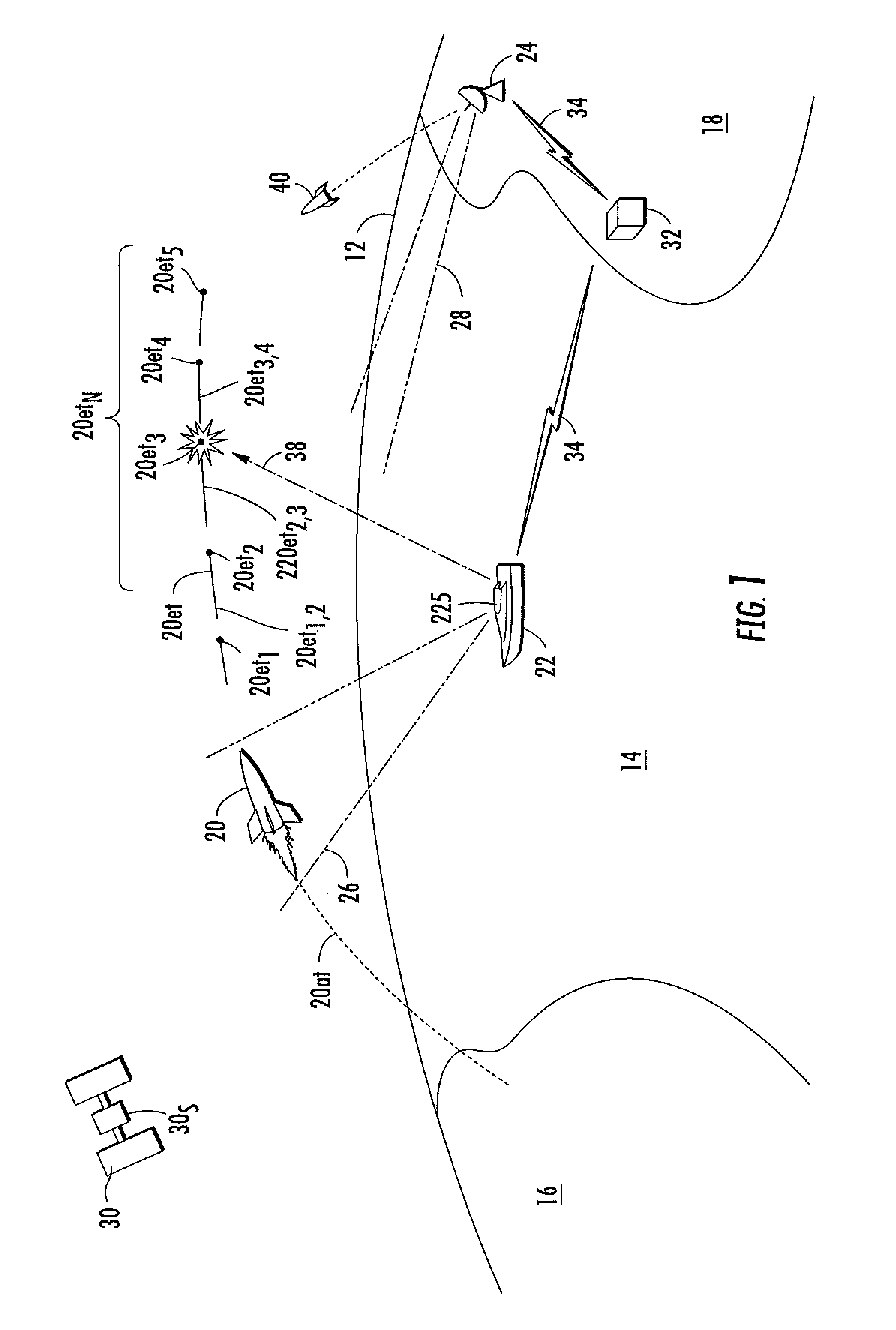
[0012]FIG. 1 is a simplified view of a portion of the Earth's surface, illustrating a horizon 12, a marine or ocean portion designated generally as 14, a first land mass designated generally as 16, and a second land mass designated generally as 18. In the scenario of FIG. 1, a hostile missile 20 was launched from land mass 16 and followed an actual track illustrated as 20at. One or more sensors detect and track the target missile 20. A first sensor illustrated as 22S is mounted on a friendly ship 22, and a second land-based sensor is illustrated as 24. The sensors may be radar sensors, but may also be of other types, such as a satellite-borne Overhead Non-Imaging InfraRed (ONIR) sensor 30S on a satellite 30. Sensor 22S scans or views over an angle illustrated as 26, which includes the hostile missile 20. Land-based sensor 24 also scans the region (28).

[0013]In the scenario of FIG. 1, the various sensors communicate with each other and with a control center, illustrated as a block 32...


PUM


Abstract

A method for engaging a hostile missile with an interceptor missile includes mathematically dividing an estimated target trajectory into portions, the junction of each portion with the next defining a possible intercept point. The engagement for each possible intercept point is modeled, to generate a probability of lethal object discrimination which is processed to generate a probability of intercept for each of the possible intercept points. The intercept point having the largest probability of intercept defines a selected intercept point from which intercept missile launch time is calculated, interceptor missile guidance is initialized, and the interceptor is launched at the calculated launch time and under the control of the interceptor missile guidance. Also, a method for estimating discrimination performance of a system of sensors includes generating sensor data signal-to-noise ratio and an aspect angle between the sensor and a lethal object. A table of probability of lethal object discrimination is generated as a function of the signal-to-noise ratio and aspect angle. The signal-to-noise ratio and the aspect angle are quantized into bins and the table with at least the signal-to-noise ratio and the aspect angle is entered to determine the probability of lethal object discrimination.

Description

FIELD OF THE INVENTIONBackground of the Invention[0001]Ballistic and intercontinental missiles have the capability of carrying nuclear, biological or chemical weapons. The severe consequences on an industrialized nation of a missile attack with such weapons makes it imperative that thought be given to possible methods for interception.[0002]A traditional missile is unitary, meaning that each missile carries one non-separating lethal warhead or reentry vehicle. One of the problems with defense against missile attack is that the attacker can deploy a cloud of chaff and / or multiple decoy objects during missile flight to confound identification of the actual lethal warhead within the cloud. In the case of Multiple Independently Targeted Reentry Vehicles, the missile may carry a plurality of lethal objects, and dispense multiple decoy objects.[0003]Identification of a target missile or warhead(s), and guidance of an interceptor missile to the lethal portion(s) of the payload are desired....

Claims


Application Information

Patent Timeline
Patent Type & Authority Patents(United States)
IPC IPC(8): F41G7/00G01S7/40F42B15/01G01S7/00F42B15/00
CPCF41G7/007F41G7/30F42B15/01
Inventor SZABO, RENEEPEDERSEN, CHRISTIAN E.COOPER, WADE E.
Owner LOCKHEED MARTIN CORP
Learn More