Methods and apparatus for switching a transponder to an active state, and asset management systems employing same

a transponder and active state technology, applied in the field of transponders, can solve the problems of all the electronic components of the rfid tag in the system being awakened, and achieve the effects of reducing total energy consumption, extending battery life or other charge storage device life, and eliminating shelf maintenance on the active rfid tag

Active Publication Date: 2011-01-25
UNIVERSITY OF PITTSBURGH
View PDF15 Cites 12 Cited by
  • Summary
  • Abstract
  • Description
  • Claims
  • Application Information

AI Technical Summary

Benefits of technology

[0009]The present invention overcomes at least two problems associated with (1) current active RFID tags, and (2) current active RFID tag wake-up protocols. The first problem is that in current RFID tags, an active RF receiving element must always be awake to anticipate a wake-up signal for the balance of the tag electronics. The present invention uses a passive circuit to eliminate the need for an “always on” active RF receiving element to anticipate a wake-up signal for the balance of the tag electronics. This solution allows the entire active RFID tag to have all circuit elements in a sleep (standby) state, thus drastically extending battery life or other charge storage device life and thus essentially eliminating shelf maintenance on the active RFID tag. The second problem is that in current active RFID tag systems, the electronics of all of the RFID tags in a system are awakened in response to wake-up signals even if the signal is not intended for a particular tag or tags. The present solution provides a major energy saving circuit that eliminates the need to wake up all of the RFID tags in response to each wake-up signal. This circuit thus reduces total energy consumption of an active RFID tag (or sensor) system or collection of devices by allowing all non-addressed tags (sensors) to remain in a sleep (standby) state, thereby reducing total system or collection energy. This second circuit can be used in conjunction with the first passive circuit mentioned above or in conjunction with any existing active RFID tag (sensor) systems. Thus, the elements of the present invention capitalize on the benefits of an active RFID tag while eliminating the problems discussed above, thus moving active RFID tags closer to a passive tag operation.
[0015]In another embodiment, the method further includes receiving at least one additional RF signal and converting the at least one additional RF signal into at least one additional DC signal without requiring the consumption of power from the power source or another power source within or connected to the transponder apparatus. In this embodiment, the at least one RF signal and each of the at least one additional RF signals have different frequencies, and the providing step comprises providing the wake-up signal to the electronic device to cause the electronic device to move from the inactive, sleep state to the active state only in response to a logical combination of the at least one DC signal and one or more of the at least one additional DC signals. Alternatively, the wake-up signal may be provided to the electronic device only if the at least one DC signal and the at least one additional DC signals are created in a particular sequence and / or if the at least one RF signal and each of the at least one additional RF signals are received in a particular sequence.

Problems solved by technology

The first problem is that in current RFID tags, an active RF receiving element must always be awake to anticipate a wake-up signal for the balance of the tag electronics.
The second problem is that in current active RFID tag systems, the electronics of all of the RFID tags in a system are awakened in response to wake-up signals even if the signal is not intended for a particular tag or tags.

Method used


Image

  • Methods and apparatus for switching a transponder to an active state, and asset management systems employing same
  • Methods and apparatus for switching a transponder to an active state, and asset management systems employing same
  • Methods and apparatus for switching a transponder to an active state, and asset management systems employing same

Examples


Embodiment Construction

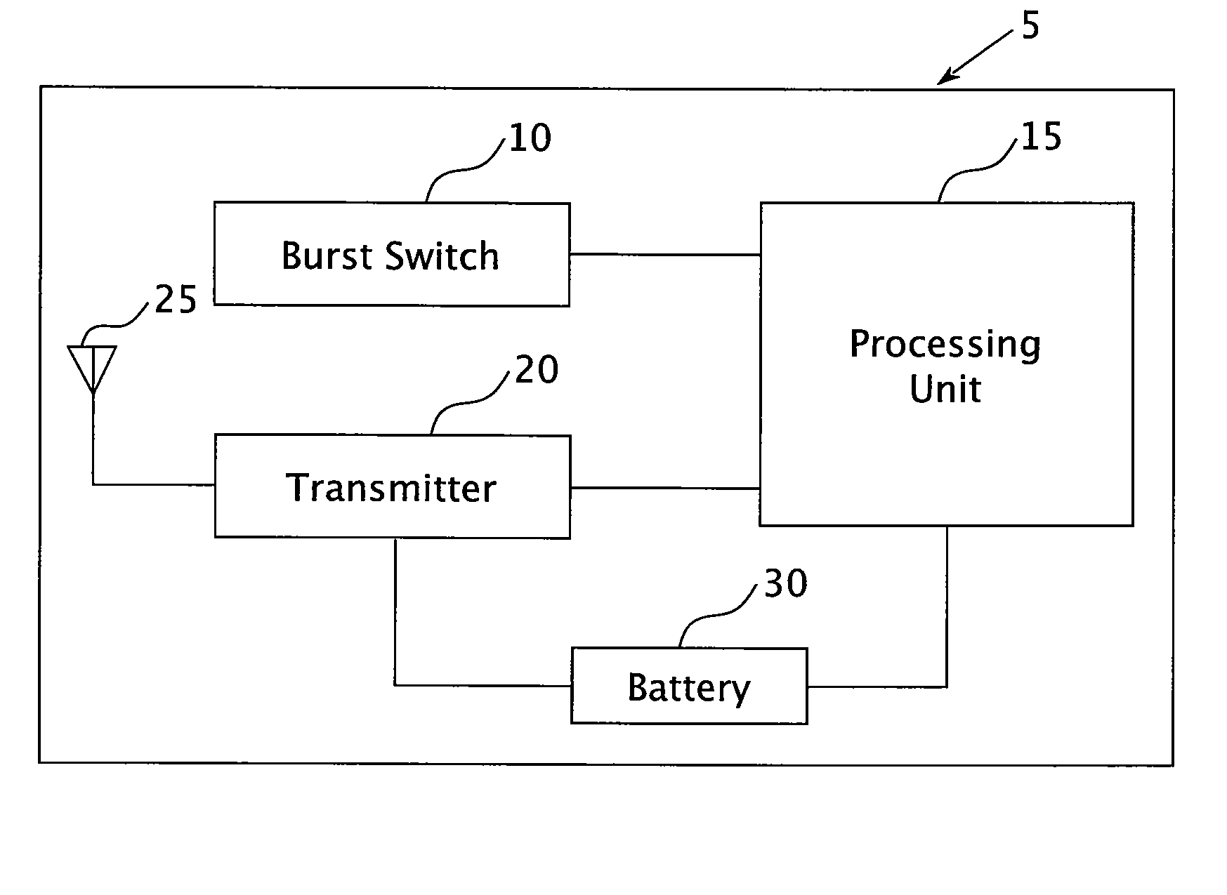
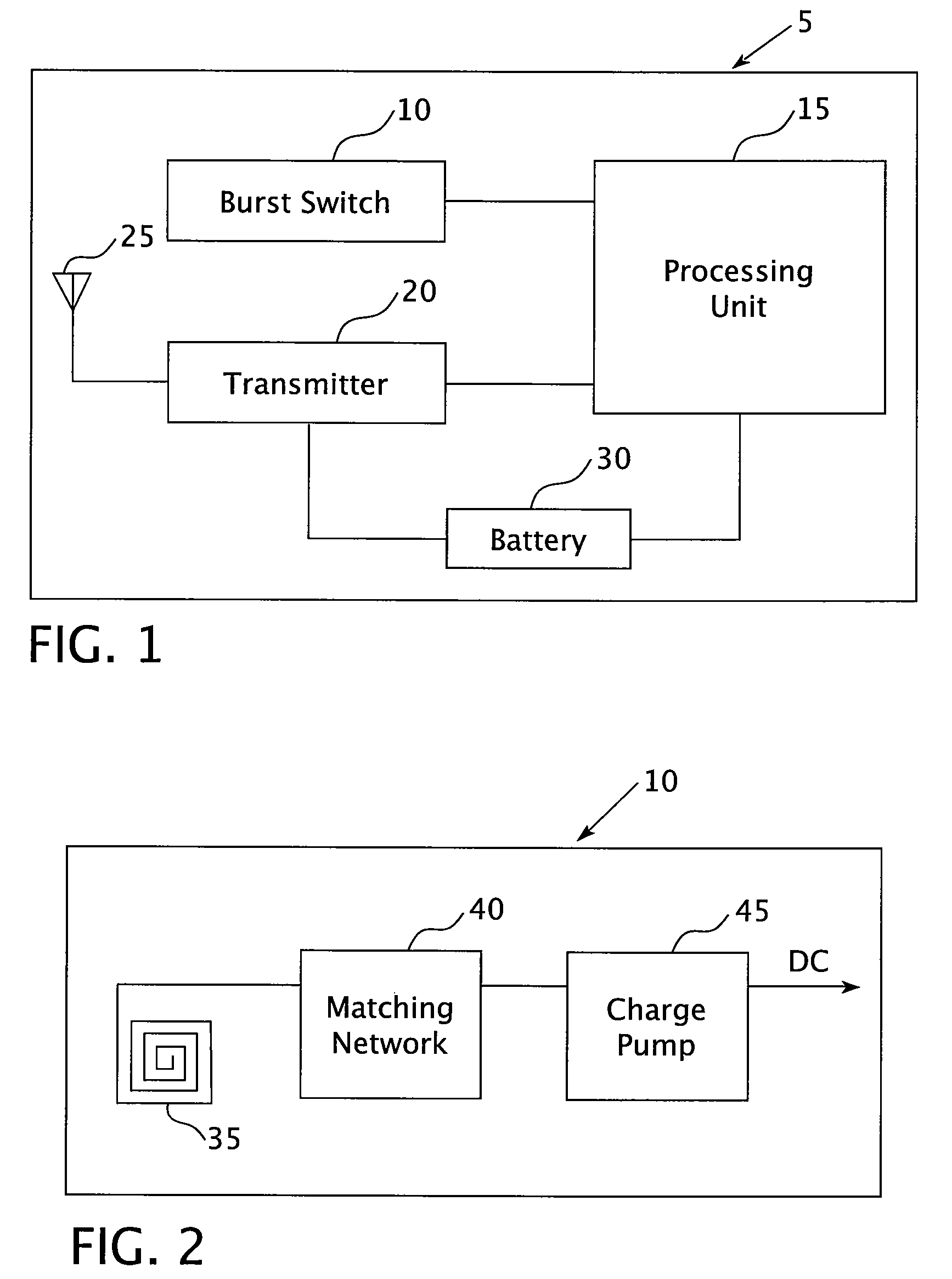
[0034]FIG. 1 is a block diagram of an RF transponder 5 according to one embodiment of the present invention. The RF transponder 5 includes a burst switch 10, which is described in more detail in connection with FIG. 2. The burst switch 10 is in electronic communication with a processing unit 15, which may be, without limitation, a microprocessor, a microcontroller, or some other type of processor device. The processing unit 15 may further be another type of electronic device, such as a CMOS device or any other electronic circuit element provided on, for example, a semiconductor substrate or printed circuit board (PCB), which performs a particular function or functions. The processing unit 15 is capable of being placed into an inactive, sleep state where the current drawn by it is at a minimum. In addition, the processing unit 15 may be woken up, i.e., moved from the inactive, sleep state to an active state, upon receipt of an external input signal. An RF transmitter 20 is in electro...


PUM


Abstract

A transponder that may be used as an RFID tag includes a passive circuit to eliminate the need for an “always on” active RF receiving element to anticipate a wake-up signal for the balance of the transponder electronics. This solution allows the entire active transponder to have all circuit elements in a sleep (standby) state, thus drastically extending battery life or other charge storage device life. Also, a wake-up solution that reduces total energy consumption of an active transponder system by allowing all non-addressed transponders to remain in a sleep (standby) state, thereby reducing total system or collection energy. Also, the transponder and wake-up solution are employed in an asset tracking system.

Description

CROSS-REFERENCE TO RELATED APPLICATION[0001]This application claims the benefit of U.S. Provisional Application No. 60 / 776,046, entitled “Methods and Apparatus for Switching a Transponder to an Active State, and Asset Management Systems Employing Same,” which was filed on Feb. 23, 2006, the disclosure of which is incorporated herein by reference.GOVERNMENT CONTRACT[0002]This work was supported in part by a grant from NASA under Contract No. NNK040AZ9C. The United States government may have certain rights in the invention described herein.FIELD OF THE INVENTION[0003]The present invention relates to transponders, such as RFID tags, and in particular to methods and apparatus for switching a transponder to an active state and asset managements system that employ such transponders.BACKGROUND OF THE INVENTION[0004]The use of radio frequency identification (RFID) systems is expanding rapidly in a wide range of application areas. RFID systems consist of a number of radio frequency tags or t...

Claims


Application Information

Patent Timeline
Patent Type & Authority Patents(United States)
IPC IPC(8): G08B13/14
CPCG06K19/0707G06K19/0712G06K19/0713G06K19/0723
Inventor MICKLE, MARLIN H.JONES, ALEX K.CAIN, JAMES T.HAWRYLAK, PETER J.MARX, FRANKHOARE, RAYMOND R.
Owner UNIVERSITY OF PITTSBURGH
Why Eureka
Try Eureka