Geothermal Cooling System for an Energy-Producing Plant

a technology of geothermal cooling and energy-producing plants, which is applied in the direction of domestic cooling apparatus, lighting and heating apparatus, machines/engines, etc., can solve the problems of limited power plant locations, high water treatment costs, and cooling towers of the prior, so as to reduce the cost of water treatment, and eliminate the time and expense of obtaining

Inactive Publication Date: 2010-08-26
GUTH DAVID
View PDF31 Cites 9 Cited by
  • Summary
  • Abstract
  • Description
  • Claims
  • Application Information

AI Technical Summary

Benefits of technology

[0010]Another object is to eliminate cooling tower costs and maintenance and related equipment.
[0011]Yet another object is to provide a condensate cooling system which decreases the expense of water treatment.
[0012]A further object of this invention is to decrease or eliminate the time and expense of obtaining local authorization in the construction and use of cooling towers.

Problems solved by technology

A water source, such as a lake or municipal supply, must be readily available to provide the necessary water, and consequently, locations of power plants are limited.
In addition, the cooling water must be treated for contaminants to avoid damage to pumps, valves, and auxiliary equipment and to minimize pipe corrosion and because the make-up water is substantially untreated, water treatment costs are considerably high.
Cooling towers of the prior art have a number of problems and shortcomings.
This can have a harmful effect, including that pollutants are discharged into the body of water, but also because when the used water is discharged into a lake or stream it raises the temperature of that body of water.
Yet another shortcoming of cooling towers in the prior art is the time and expense involved in treating the water for contaminants.
Another problem in the cooling tower prior art is the ability to procure the necessary licensing / permits from local governments with respect to the installation and use of cooling towers.

Method used


Image

  • Geothermal Cooling System for an Energy-Producing Plant
  • Geothermal Cooling System for an Energy-Producing Plant
  • Geothermal Cooling System for an Energy-Producing Plant

Examples


Embodiment Construction

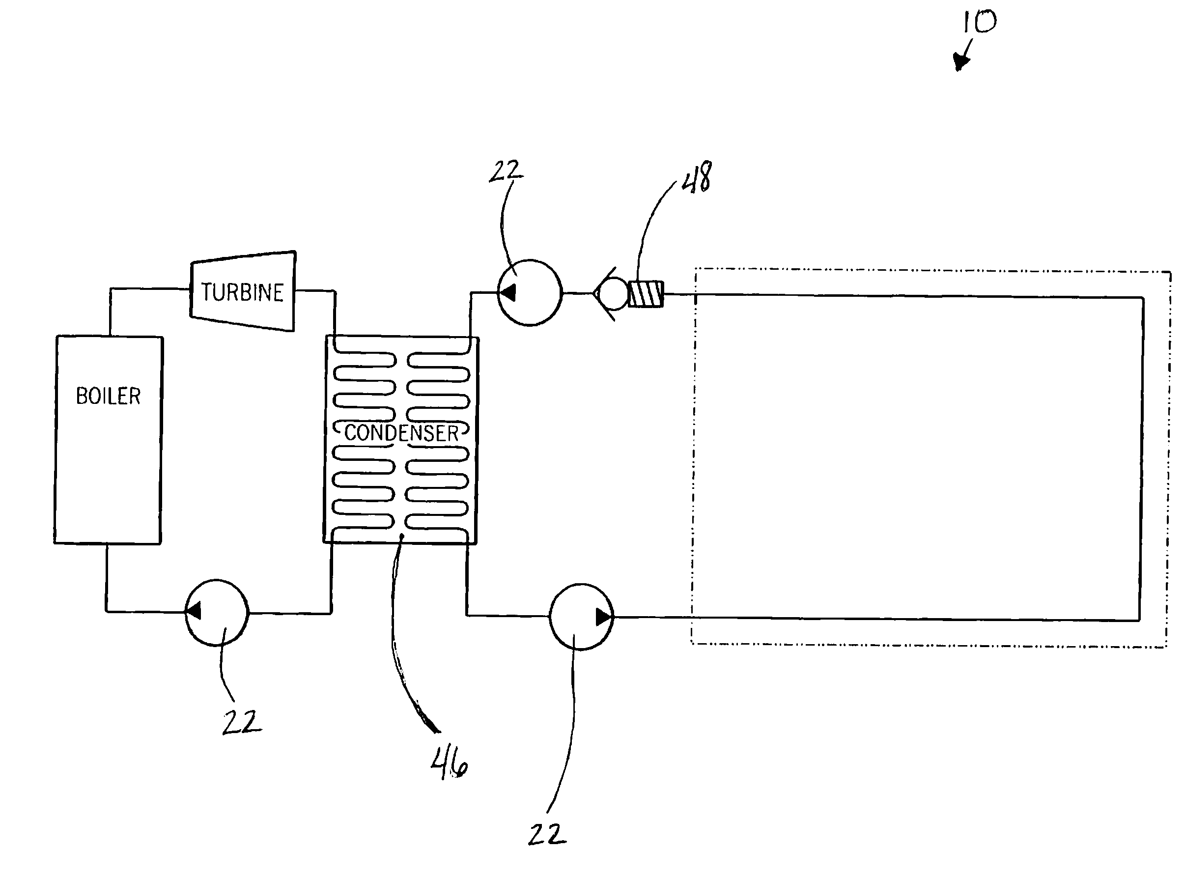
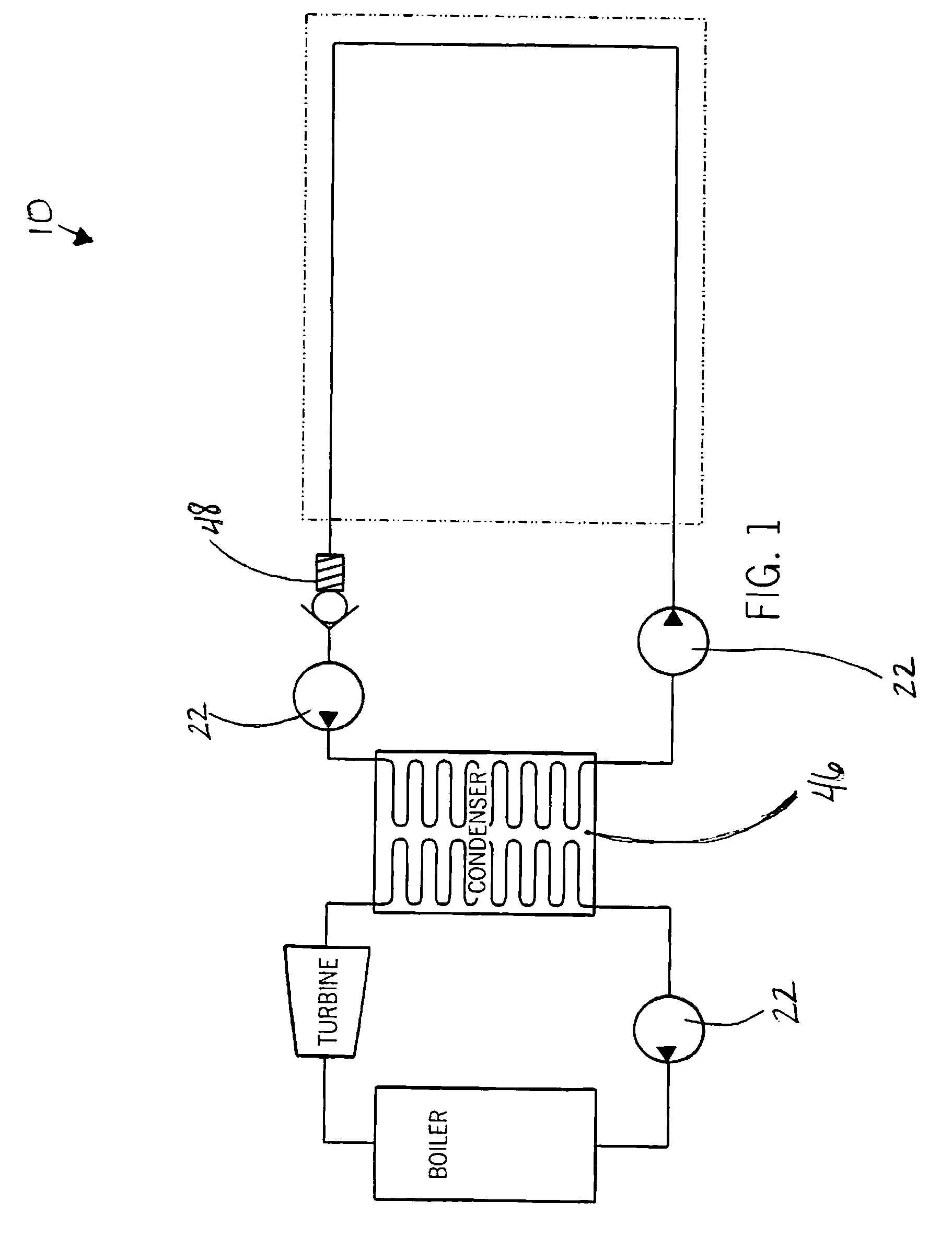
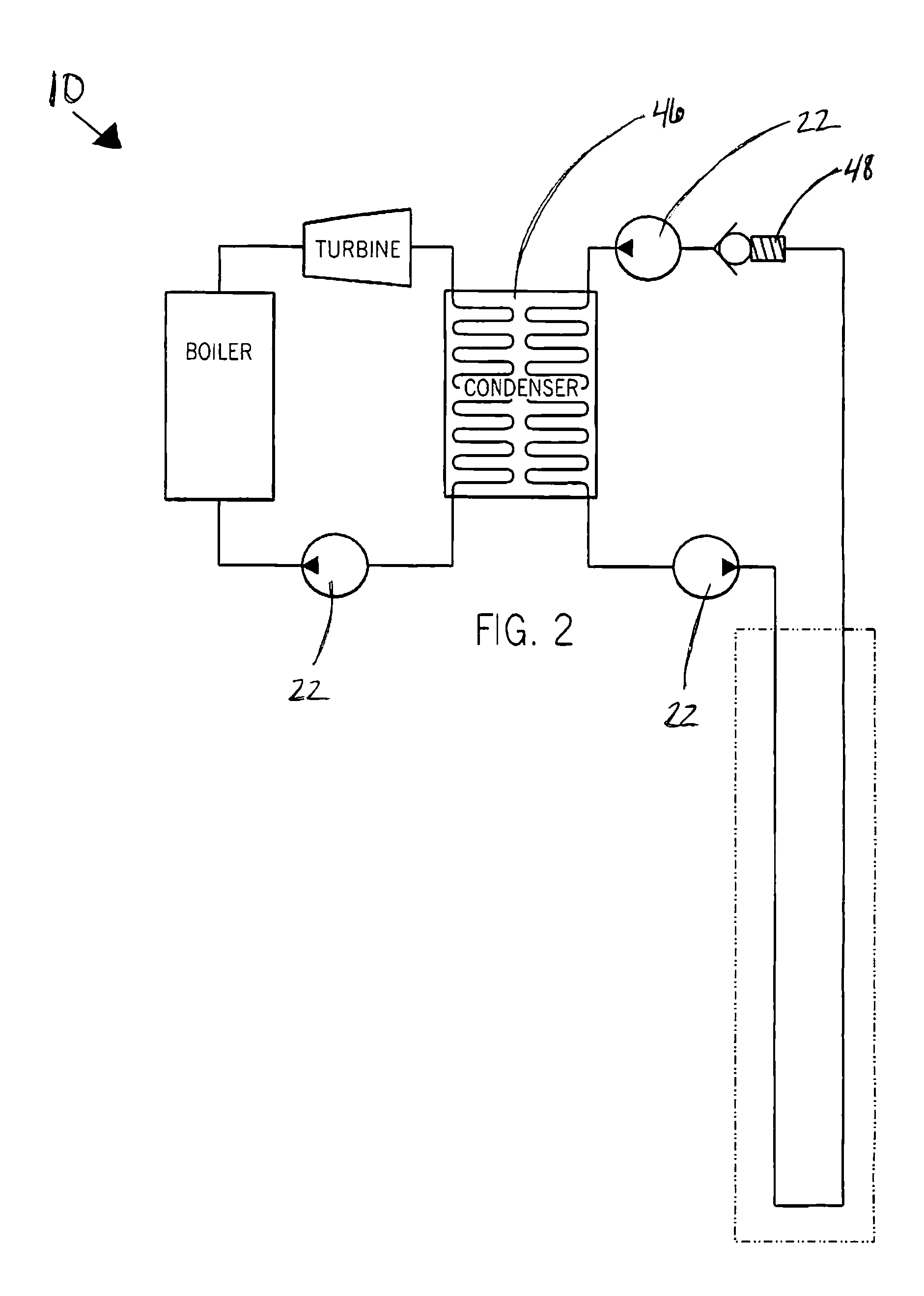
[0024]FIGS. 1-5 illustrate a preferred embodiment of an electrical-utility steam-turbine power-plant condensate cooling system (10) having subterranean horizontal tunneling having multiple connecting portions (24), an inlet portion (12), a discharge and cooling portion (14). Substantially all of the cooling portion (14) is a closed-loop tunneling system (16) beneath the surface (18) of the Earth as seen in FIGS. 1 and 3. Water (20) substantially fills the closed-loop system (16) and pump (22) facilitates flow through the closed-loop system (16) whereby water (20) flowing through the tunneling (16) is geothermally cooled.

[0025]As illustrated in FIGS. 1 and 3, a highly preferred embodiment has tunneling (16) configured in a generally horizontal direction. In an alternate embodiment, tunneling (16) is in a generally vertical configuration and is substantially located within the Earth as seen in FIGS. 2 and 4. The bed of tunnels (16) is ideally in a horizontal configuration but can be c...


PUM


Abstract

An improved electrical-utility steam-turbine power-plant cooling system including a condenser with heat-exchange surfaces and cooling means. The cooling means has a closed-loop system with an intake, a discharge and a cooling portion. Substantially all of the cooling portion is tunneling beneath the surface of the Earth. Water substantially fills the closed-loop system and a pump facilitates flow through the closed-loop system whereby water flows through the tunneling and is geothermally cooled.

Description

FIELD OF THE INVENTION[0001]This invention is related generally to a closed-loop condensate cooling system for steam-turbine power-plants and more particularly to a closed-loop cooling system which utilizes geothermal temperature differential to cool water contained within the closed-circuit cooling system.BACKGROUND OF THE INVENTION[0002]The current method in cooling condensate of a steam-driven turbine is by use of a water cooling tower. Cooling towers are large towers over which hot condensate cooling water is pumped to the roof of the tower and cascades down the outer portion of the tower over a diffusing structure, such as fins or a mesh. Traditionally, cooling towers have a plurality of large fans located on the roof of the tower which pull air through the outer skin of the cooling tower causing evaporative cooling of the hot water. The relatively cool water collects in a basin at the bottom of the cooling tower and is recirculated through the condensate cooling system.[0003]T...

Claims


Application Information

Patent Timeline
Patent Type & Authority Applications(United States)
IPC IPC(8): F28B9/02F01K9/00F28C1/14
CPCF01K9/003Y02E10/12F24J3/081F24T10/10Y02E10/10
Inventor GUTH, DAVID
Owner GUTH DAVID
Why Eureka
Try Eureka