
Traffic protection in a communication network

a communication network and traffic protection technology, applied in data switching networks, frequency-division multiplexes, instruments, etc., can solve the problems of easy degradation of mwr link quality, link breakage, no capacity or bandwidth flexibility, etc., and achieve the effect of improving loop protection

Inactive Publication Date: 2011-01-25
RPX CORP
View PDF9 Cites 16 Cited by
  • Summary
  • Abstract
  • Description
  • Claims
  • Application Information

AI Technical Summary

Benefits of technology

[0015]Consequently, it is a concern of the present invention, for example, that it may remove at least some of the above drawbacks. It is a further concern of the present invention, for example, to provide accordingly improved loop protection.
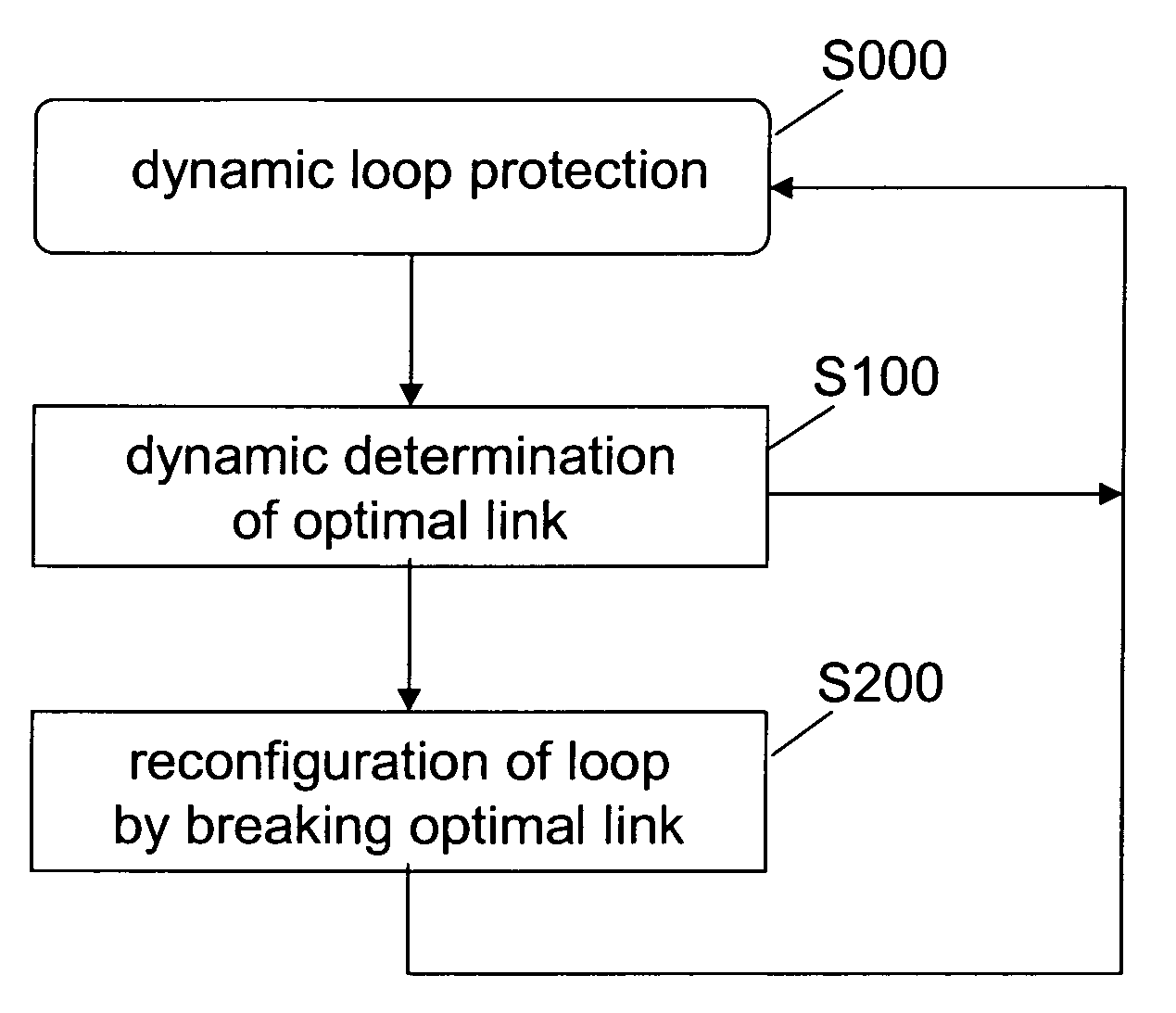
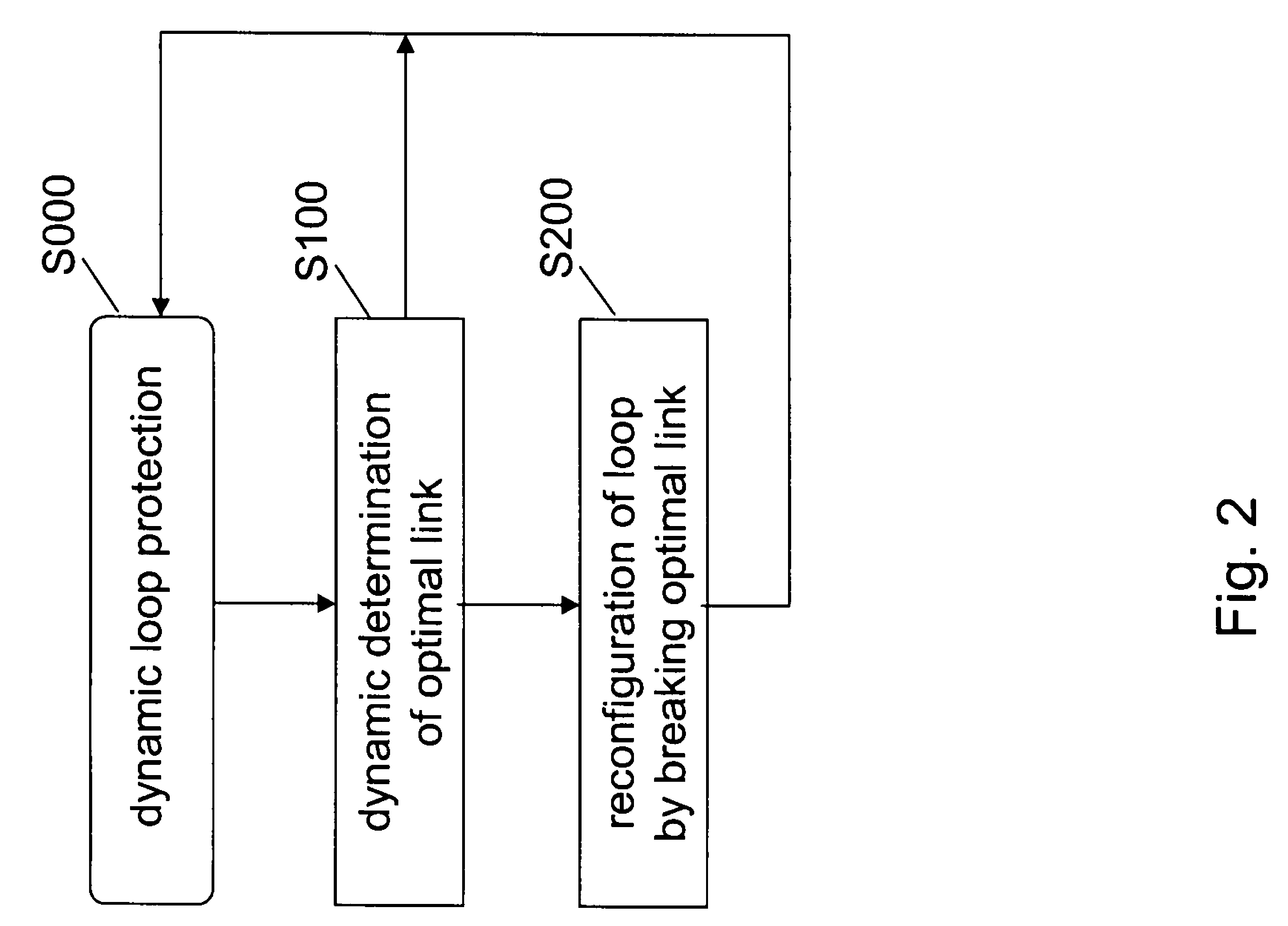
[0021]According to embodiments of the present invention, a loop such as e.g. an Ethernet loop may be dynamically broken at an optimal link with respect to instantaneous link capacities. In view of a corresponding optimization criterion, this could be done so that the capacity loss by loop breaking is minimized and so the available capacity in the loop is maximized. The location of the loop break may be dynamically and / or automatically adapted to changes in the instantaneous link capacities and / or to load conditions at the nodes of the loop. Further, besides any kind of link state protocol, a spanning tree algorithm such as e.g. STP and RSTP may be used. Thereby, a fast protection scheme may be provided, which may automatically and rapidly react on total link or node losses in addition to link condition changes.

Problems solved by technology

MWR links are sensitive against bad weather conditions (e.g. heavy rain), which may easily degrade the MWR link quality.
This usually leads to a link break and requires the switching of the traffic (or part of the traffic) to an alternative route to avoid service degradation or to minimise an unfavourable effect to the service.
Capacity allocations (e.g. including bandwidth on links) are fixed, which means there is no capacity or bandwidth flexibility.
The capability of adaptive radio modulation to maintain data transfer in bad transmission conditions can not be exploited.
Therefore, decreasing capacity on a link would lead to a complete loss of certain links.
However, there exists a problem that loops are not allowed in Ethernet-based transport networks, since Ethernet frames would circulate forever.
Known solutions in the field of Ethernet-based loop and Ethernet loop protection like Resilient Packet Ring (RPR) and Ethernet Automatic Protection Switching (EAPS) do however not fit well with or are not giving the full benefit in hierarchical network architectures such as those of a radio access network, where there is no (or just a very limited amount of) traffic between the nodes in the loop and the main portion of traffic is upstream traffic.
There are no dedicated protection resources, and both rings transport traffic using shortest paths.
This is not optimal from load balancing point of view, especially in hierarchical architectures, such as for example hierarchical RAN architectures, because the optimal place for the break would be in the middle of the ring in respect of the master node.
In addition, EAPS and similar solutions are on / off-type mechanisms without adaptation to available link capacities in the ring, therefore e.g. not allowing any load balancing.
However, both STP and RSTP are on / off-type mechanisms without adaptation to available link capacities in the ring, therefore e.g. not allowing any load balancing.
Thus, the above solutions as such are mainly suitable for links with on / off characteristic, thus being not optimum for appropriately distributing the load across the working links of a loop.

Method used


Image

  • Traffic protection in a communication network
  • Traffic protection in a communication network
  • Traffic protection in a communication network

Examples


Embodiment Construction

[0035]The present invention and exemplary embodiments thereof are described herein below with reference to the drawings representing particular non-limiting examples thereof. A person skilled in the art will appreciate that the invention is not limited to these examples, and may be more broadly applied.

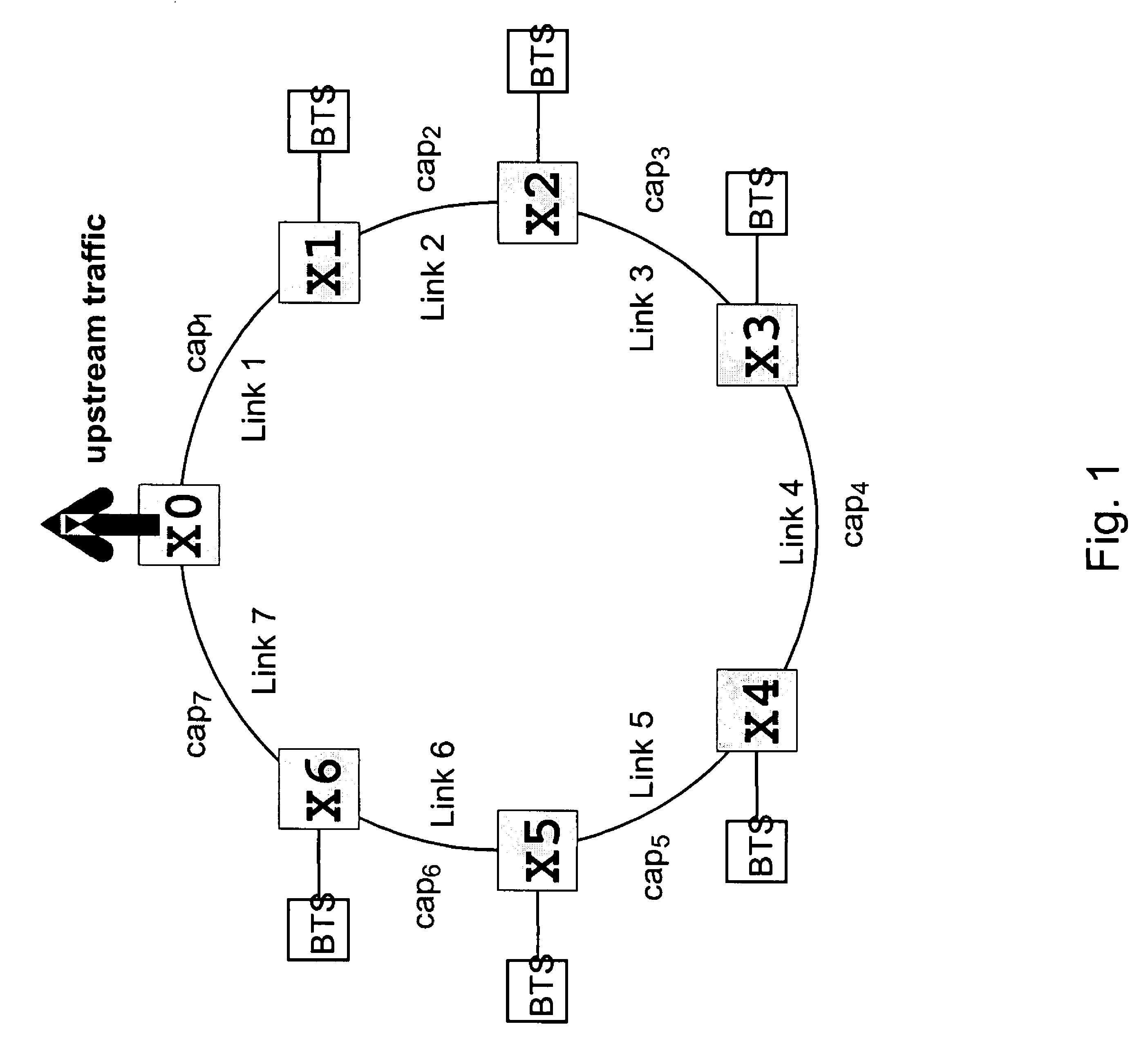
[0036]In particular, the present invention and exemplary embodiments thereof are described in relation to a loop structure (as e.g. depicted in FIG. 1) which is independent of the overall network architecture. That is, although it is referred only to the loop, the overall architecture of the underlying communication network may for example also be a network of chain, star, loop or mesh architecture / topology, in which the loop represents only a part of the overall connectivity. It is to be noted that the term loop is to be understood as a synonym for the term ring, so the description as well be transferable to any kind of rings in any kind of underlying networks. Further, Ethernet is u...


PUM


Abstract

A loop protection mechanism including dynamically determining a link connecting two adjacent nodes of a loop in a communication network in accordance with a predefined criterion, and reconfiguring the loop so that the loop is broken at the determined link which is an optimal link in terms of the predefined criterion. The breaking of the loop enables for example to utilize loop-free technologies (e.g. Ethernet) in a physical loop architecture.

Description

FIELD OF THE INVENTION[0001]The present invention relates to traffic protection in communication networks of any kind of architecture, topology and / or application area.BACKGROUND OF THE INVENTION[0002]In a communication network traffic protection can be implemented in many different ways for various network topologies (e.g. chain, star, loop and mesh topology, while a mesh consists of at least two loops). Especially loop-based networks are attractive for network operators, because they offer the capability of quite easily and cost efficiently enabling redundancy in a network consisting of a relatively large number of nodes. In loop-based networks a redundant path for each node is provided by just one additional link that closes two adjacent branches to form a loop. For example, loop protection, i.e. provision of redundancy by way of a loop structure, is used today by many mobile network operators e.g. for 2G and 3G radio access networks (RAN), where network elements like e.g. base s...

Claims


Application Information

Patent Timeline
Patent Type & Authority Patents(United States)
IPC IPC(8): G01R31/08H04L12/28H04L12/43
CPCH04L12/437H04L12/462H04L47/10
Inventor HAUENSTEIN, MARKUSKAPANEN, JOUKOBERGHOFF, GERALD
Owner RPX CORP
Learn More