
Recovery point identification in CDP environments

a recovery point and environment technology, applied in the field of recovery point identification, can solve problems such as corrupted data, and achieve the effects of identifying clean data, quick identifying clean data, and reducing the overall recovery tim

Inactive Publication Date: 2011-01-25
INT BUSINESS MASCH CORP
View PDF6 Cites 14 Cited by
  • Summary
  • Abstract
  • Description
  • Claims
  • Application Information

AI Technical Summary

Benefits of technology

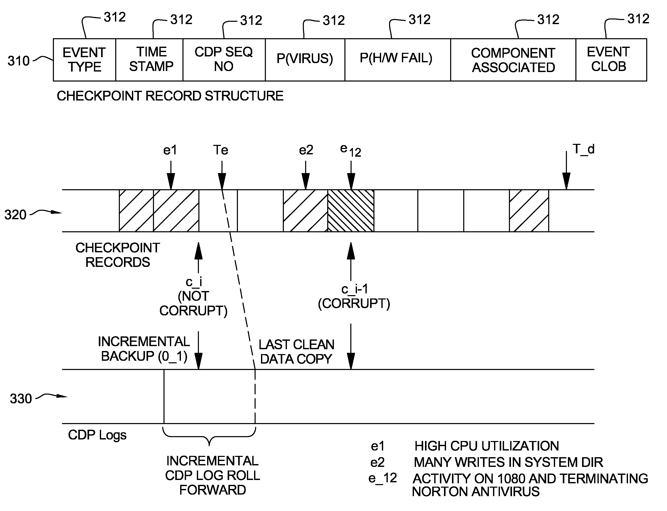
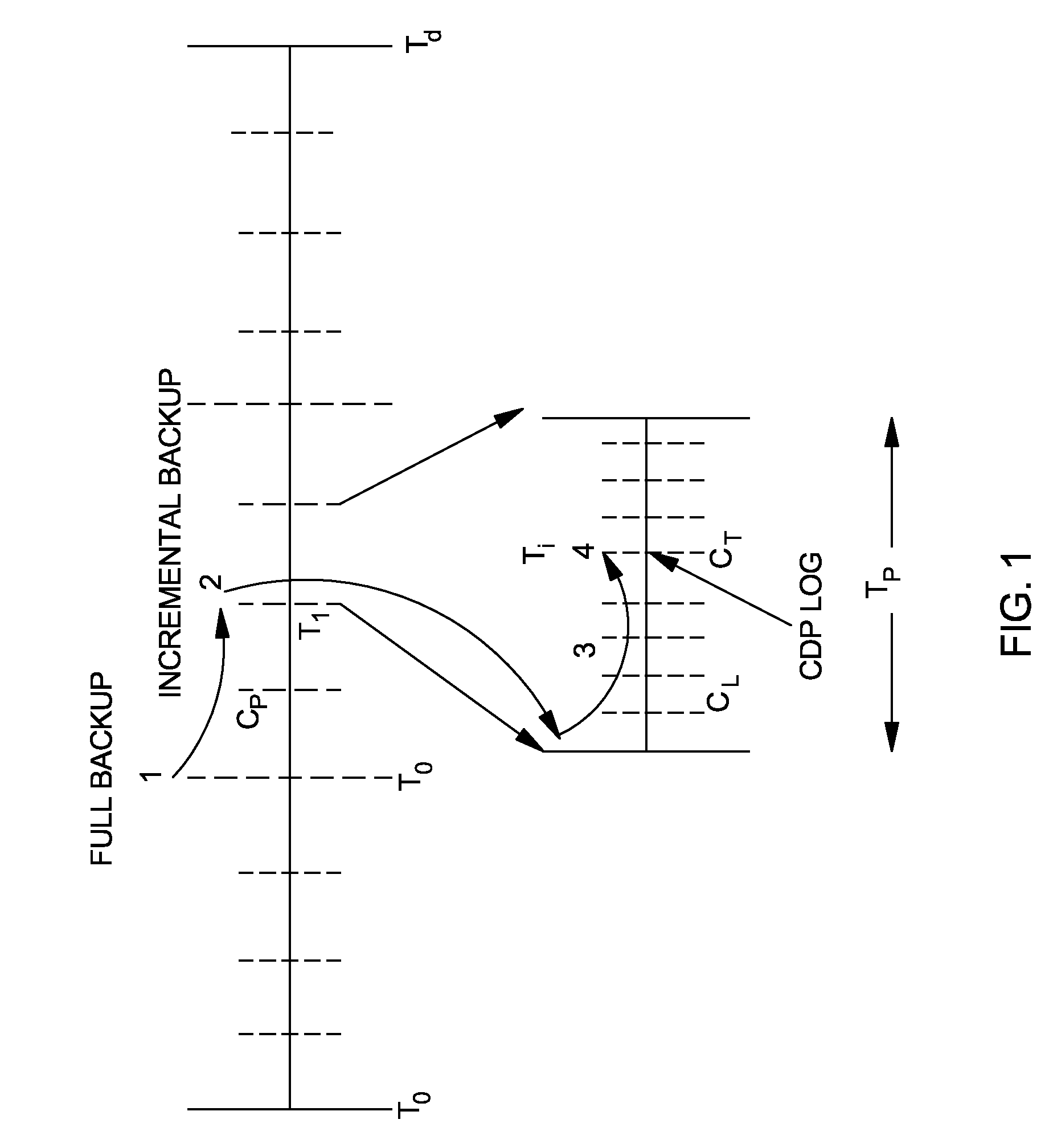
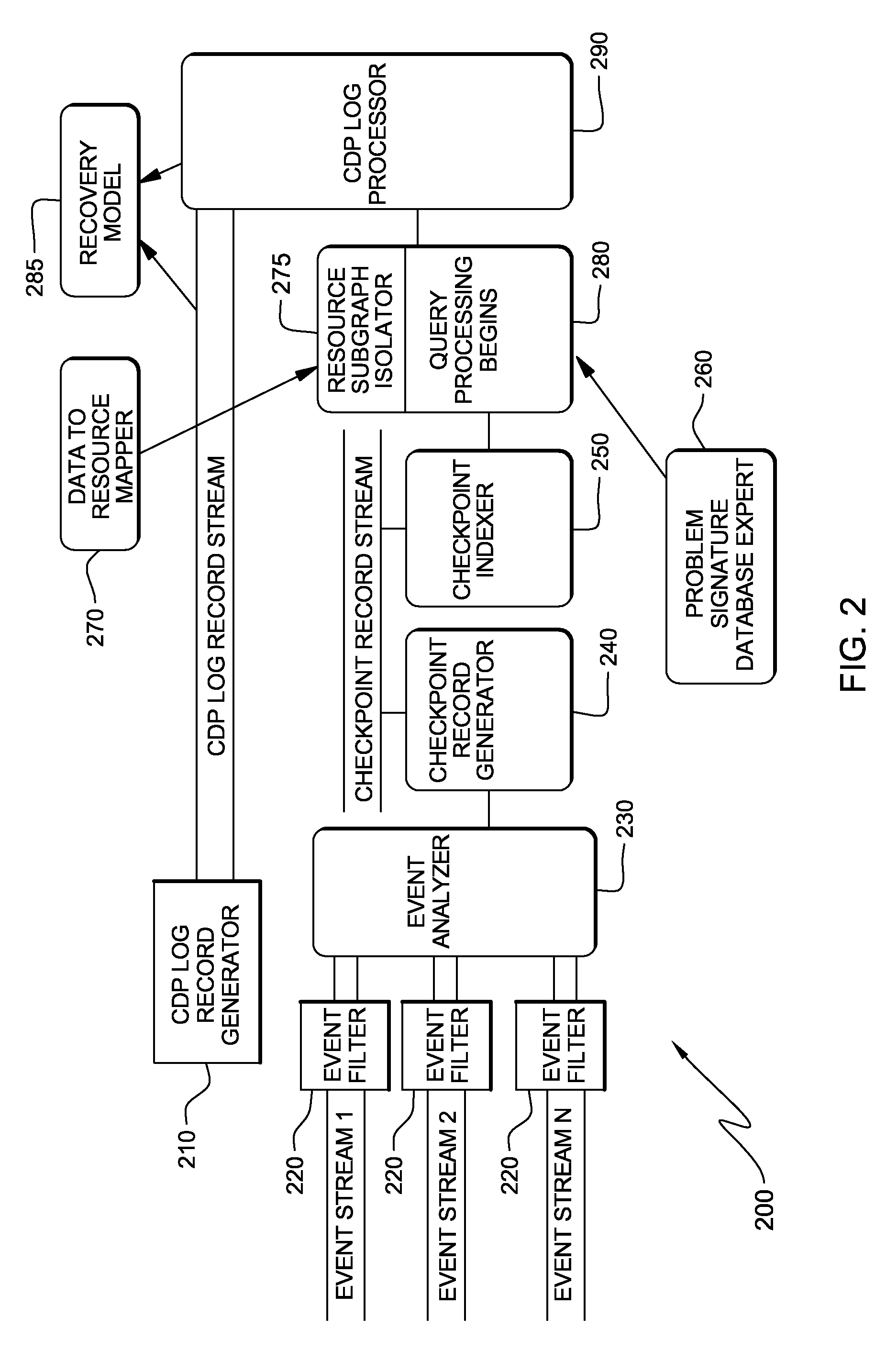
[0013]Accordingly, the embodiments of the invention provide an architecture and data scanning methods that quickly identify clean copies of data. The architecture and methods are compatible with existing CDP solutions and are extensible because they allow different applications to customize the process of identifying corrupt data. Moreover, the embodiments herein allow system administrators to decide on the trade-off between data currentness and overall recovery time. By incorporating the architecture and methods into existing CDP solutions, system administrators can cut down the overall recovery time by quickly identifying a clean copy of data. The embodiments herein can reduce the overall recovery time by many orders of magnitude.

Problems solved by technology

When identifying a data corruption problem, users find that a latest copy of data has been corrupted by some element, such as a virus attack, or a malfunctioning storage controller or disk.

Method used


Image

  • Recovery point identification in CDP environments
  • Recovery point identification in CDP environments
  • Recovery point identification in CDP environments

Examples


Embodiment Construction

[0022]The embodiments of the invention and the various features and advantageous details thereof are explained more fully with reference to the non-limiting embodiments that are illustrated in the accompanying drawings and detailed in the following description. It should be noted that the features illustrated in the drawings are not necessarily drawn to scale. Descriptions of well-known components and processing techniques are omitted so as to not unnecessarily obscure the embodiments of the invention. The examples used herein are intended merely to facilitate an understanding of ways in which the embodiments of the invention may be practiced and to further enable those of skill in the art to practice the embodiments of the invention. Accordingly, the examples should not be construed as limiting the scope of the embodiments of the invention.

[0023]The embodiments of the invention provide methods for efficient recovery point identification in CDP logs. Specifically, the methods evalua...


PUM


Abstract

The embodiments of the invention provide a method of identifying a recovery point in a continuous data protection (CDP) log. More specifically, the method begins by detecting corrupted data in the CDP log and identifying the nature of corruption. Next, the nature of corruption is mapped to applications to identify components that may have caused the corrupted data. The method then finds a time instance of uncorrupted data in the components. Specifically, this can include searching CDP log entries in an order independent of log event age. Alternatively, the process of finding the time instance can include creating a data image of a first copy of uncorrupted data and sequentially apply entries of the CDP log until the corrupted data is reached.

Description

BACKGROUND[0001]1. Field of the Invention[0002]The embodiments of the invention relate to recovery point identification in continuous data protection (CDP) environments.[0003]2. Description of the Related Art[0004]When identifying a data corruption problem, users find that a latest copy of data has been corrupted by some element, such as a virus attack, or a malfunctioning storage controller or disk. In cases of data corruption, a clean copy of the most current data must be retrieved. However, the recovery time is dependent on how quickly the most current clean copy of data can be identified and retrieved.[0005]Data protection can be achieved by taking continuous or periodic snapshots of the data as it is being updated. Block level, file level, logical volume level, and database level data replication / recovery mechanisms are prominent data protection mechanisms.[0006]Such data protection mechanisms vary with respect to their support for different data granularities, transactional su...

Claims


Application Information

Patent Timeline
Patent Type & Authority Patents(United States)
IPC IPC(8): G06F7/00
CPCG06F11/1471G06F11/1469
Inventor ROHIT, JAINROUTRAY, RAMANI R.VERMA, AKSHATVORUGANTI, KALADHAR
Owner INT BUSINESS MASCH CORP
Learn More