

Substrate processing apparatus
a processing apparatus and substrate technology, applied in the direction of chemistry apparatus and processes, cleaning processes and apparatus, cleaning using liquids, etc., can solve the problem of taking a fixed amount of time to carry the substrate, and achieve the effect of quick carrying the substrate in and ou
- Summary
- Abstract
- Description
- Claims
- Application Information
AI Technical Summary
Benefits of technology
Problems solved by technology
Method used
Image

Examples
first embodiment
(1) First Embodiment
[0081]A substrate processing apparatus according to a first embodiment will now be described with reference to drawings.
[0082](1-1) Configuration of the Substrate Processing Apparatus
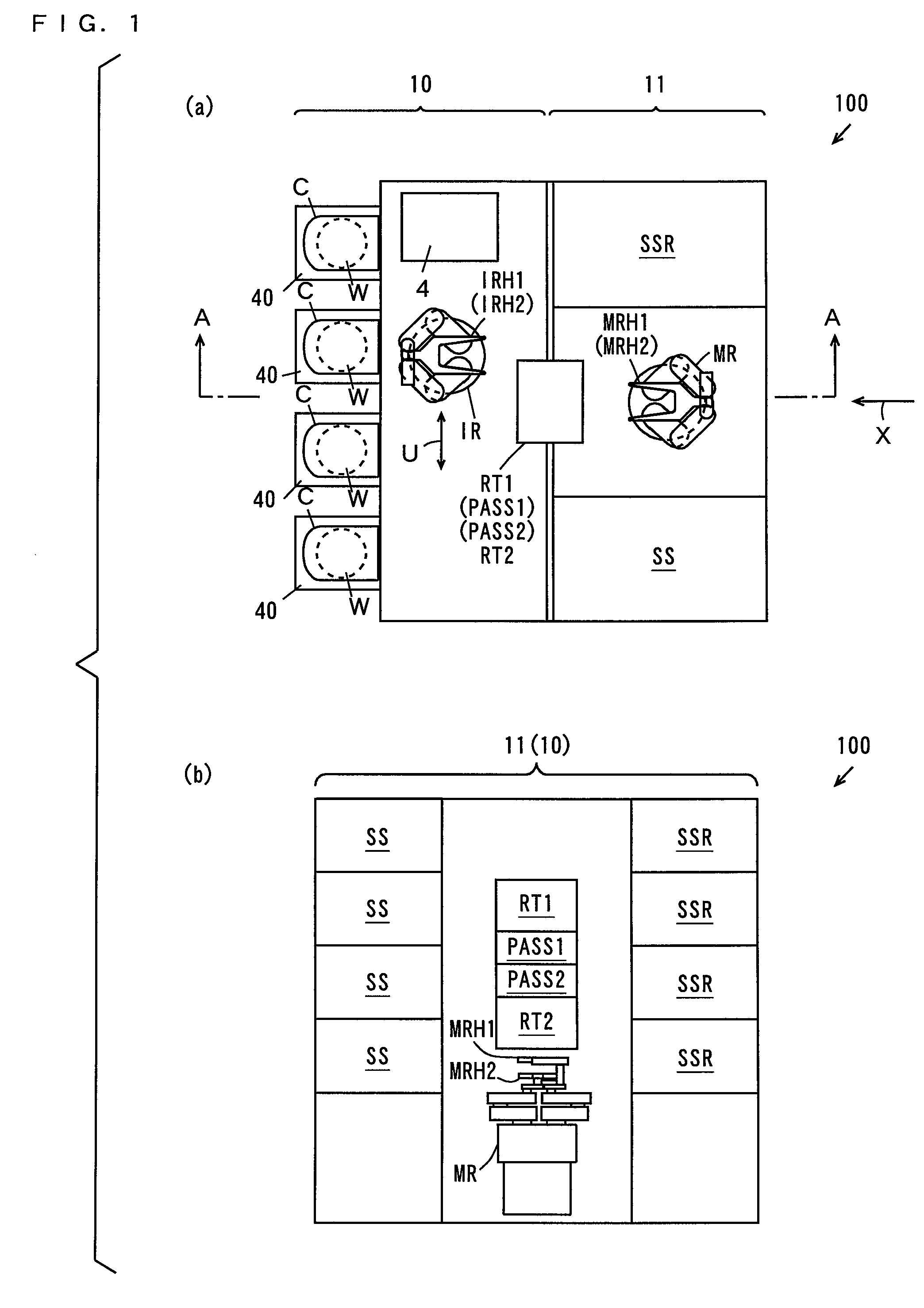
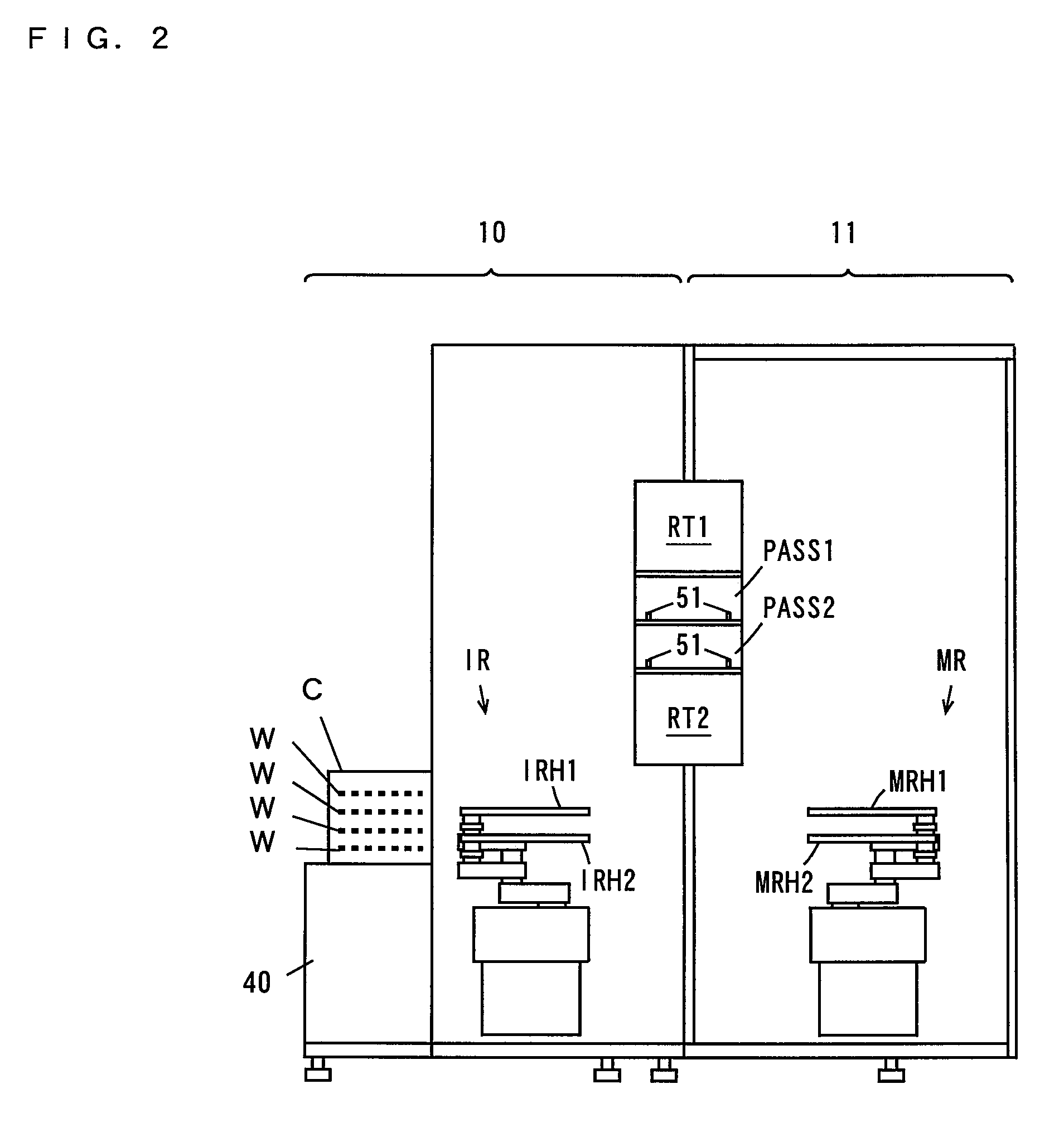
[0083]FIG. 1(a) is a plan view of the substrate processing apparatus according to a first embodiment of the present invention, and FIG. 1(b) is a schematic side view in which the substrate processing apparatus of FIG. 1(a) is seen from a direction of the arrow X. FIG. 2 is a diagram schematically showing a cross section of FIG. 1(a) taken along the line A-A.
[0084]As shown in FIG. 1(a), the substrate processing apparatus 100 includes an indexer block 10 and a processing block 11. The indexer block 10 and the processing block 11 are provided in parallel to each other.
[0085]The indexer block 10 is provided with a plurality of carrier platforms 40, an indexer robot IR and a controller 4. Carriers C that store a plurality of substrates W in multiple stages are placed on the carrier platfo...
second embodiment
(2) Second Embodiment
[0151]For a substrate processing apparatus according to a second embodiment of the present invention, different points from the substrate processing apparatus according to the first embodiment will be described.
[0152](2-1) Configuration of the Substrate Processing Apparatus
[0153]FIG. 11(a) is a plan view of the substrate processing apparatus according to the second embodiment of the present invention, and FIG. 11(b) is a diagram that schematically shows the sectional view taken along the line B-B of FIG. 11(a). As shown in FIG. 11(a) and FIG. 11(b), the substrate processing apparatus 100a according to the second embodiment includes each two of the reversing units RT1, RT2 and the substrate platforms PASS1, PASS2.
[0154](2-2) Operations of the Main Robot
[0155]Next, a summary of the operations of the main robot MR in the second embodiment will be described by referring to FIG. 11. The main robot MR receives the unprocessed substrates W from the two substrate platfo...
third embodiment
(3) Third Embodiment
[0167]For a substrate processing apparatus according to a third embodiment of the present invention, different points from the substrate processing apparatus according to the first embodiment will now be described. The substrate processing apparatus according to the third embodiment includes reversing units RT1a, RT2a that will be shown below instead of the reversing units RT1, RT2.
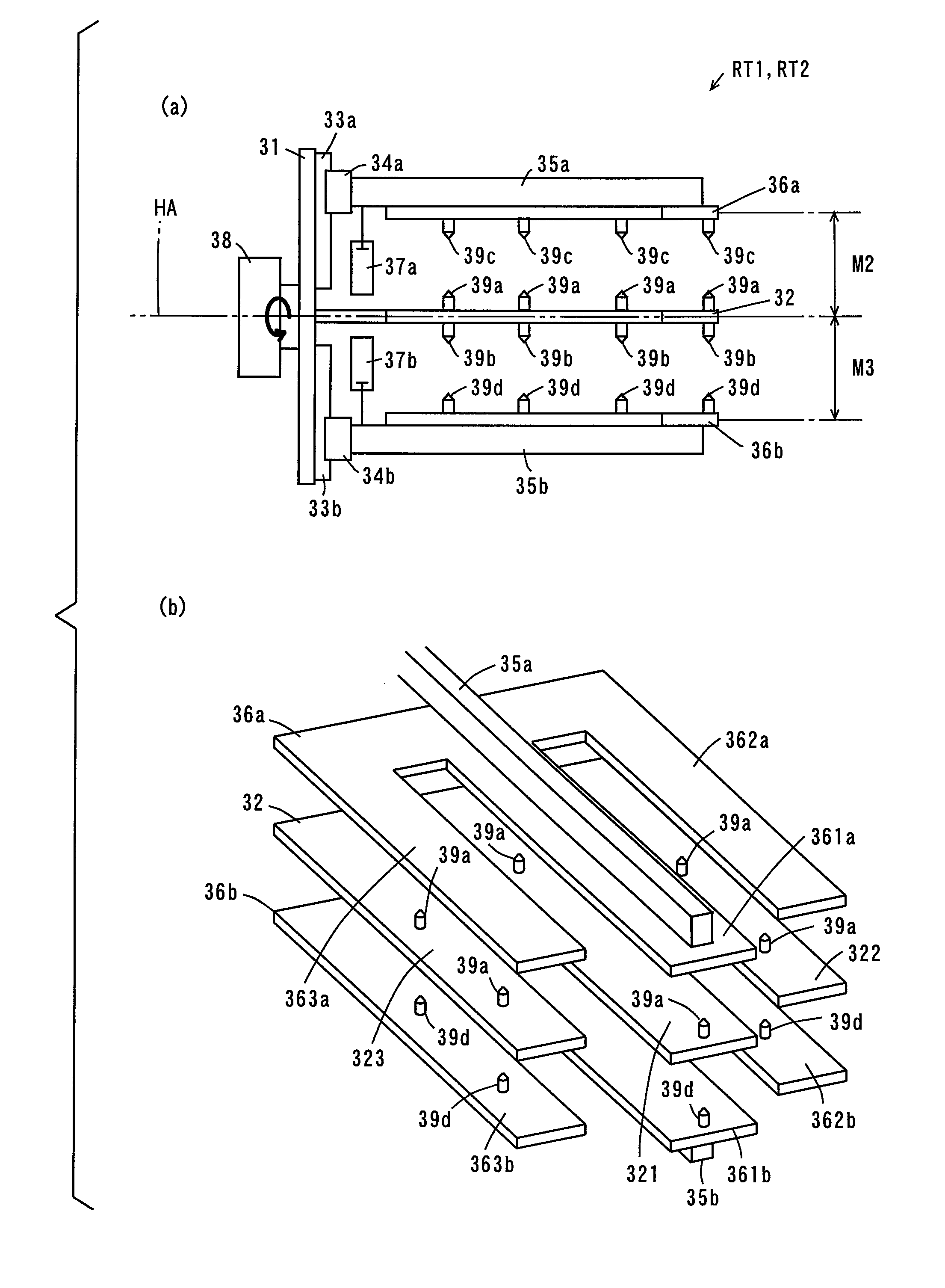
[0168]FIG. 14(a) is a side view of the reversing unit RT1a, RT2a and FIG. 14(b) is a perspective view of the reversing unit RT1a, RT2a. For the reversing unit RT1a, RT2a, different points from the reversing unit RT1, RT2 will be explained by use of FIG. 14(a) and FIG. 14(b). Note that the reversing units RT1a, RT2a have the same configuration.
[0169]As shown in FIG. 14(a) and FIG. 14(b), the reversing unit RT1a, RT2a includes a third movable plate 41a, a fourth movable plate 41b, a pair of linear guides 42a, 42b and a pair of cylinders 43a, 43b instead of the fixed plate 32.
[0170]The th...
PUM
 Abstract
Description
Claims
Application Information