Expandable centralizer for expandable pipe string

a technology of expandable pipes and centralizers, which is applied in the direction of drilling pipes, drilling casings, borehole/well accessories, etc., can solve the problems of bow springs slipping out of alignment, affecting the expansion and the expansion of the centralizer is likely to be damaged or impaired. , to achieve the effect of reducing the clearance, reducing the plastic deformation of the collar and the bow spring connection, and reducing the diameter of the expandable collars

Active Publication Date: 2011-02-01
INNOVEX DOWNHOLE SOLUTIONS INC
View PDF37 Cites 26 Cited by
  • Summary
  • Abstract
  • Description
  • Claims
  • Application Information

AI Technical Summary

Benefits of technology

[0024]In one embodiment, the curvature of each bow spring changes along the length of the bow spring from a minimum curvature adjacent to the first end and the second end of the bow spring, to a maximum curvature near the center of the bow spring generally intermediate the first end and the second end. This embodiment may provide an expandable centralizer that is self-securing when the bow springs are collapsed to lie generally along a portion of the length of the pipe string on which the expandable centralizer is received. This self-securing capacity is due to the inwardly-directed gripping action by the portions of each bow spring immediately adjacent to its first end and to its second end as the bow spring is radially inwardly collapsed. It should be understood that the amount of grip imparted by the bow springs to the exterior of the expandable pipe as the bow springs are collapsed to lie along a portion of length of the pipe string may be determined by, among other factors, the shape of the bow springs, and specifically by the contour of the bow springs immediately adjacent to the bow spring / collar connections. In these portions, the curvature of each bow spring may be generally opposite in direction to the curvature of the middle portion of each bow spring that deploys to engage the wall of the borehole. The grip applied to the exterior surface of the expandable pipe string by the collapsed bow springs, coupled with the application or fabrication of a band to restrain the bow springs in the collapsed configuration prior to installation of the expandable pipe string into the borehole, eliminates the need for one or more stop collars to secure the expandable centralizer in its axial position on the expandable pipe string. The collapsed bow springs continue to grip the exterior of the expandable pipe string until the bow springs of the expandable centralizer are deployed. Upon deployment, the centralizer may be secured in place within the borehole by the gripping force applied by the portions of the bow springs that engage the wall of the borehole.
[0027]It should further be understood that, in one embodiment, the expandable collars of the expandable centralizer may be made so that each collar is secured in its position on the expanded pipe string. For example, but not by way of limitation, an expandable collar in which each slidably extendable pair of adjacent links has separated one from the other in a manner to cause the head of each link to move to its extreme position at the proximal end of the chamber of the adjacent link in which the head is movable, may thereby form an expanded collar imparting a grip on the exterior of the expanded pipe string. This grip by each of the slidably expanded collars of the centralizer may be achieved by, for example, making the dimensions of the head, extensions, chambers and links so that the cumulative slidable expansions of each slidably coupled pair of links approximately equals the increase in the circumference of the expanded pipe string over and above the circumference of the unexpanded pipe string. An expandable centralizer made according to this embodiment of the method may self-secure in its position on the expanded pipe string without the need for one or more stop collars to maintain its position.
[0030]It should be understood that each of the elements of the link, including, but not limited to the extension, the head, the chamber and the channel, may be curved or arcuate in the circumferential direction so that the plurality of links coupled together generally conform to the shape of a tube to minimize the clearance required to accommodate the expandable collar and the size of the annulus within which the expandable centralizer may be disposed when the bow springs are collapsed and restrained in their collapsed configuration.
[0031]Embodiments of the expandable centralizer permit expansion of the expandable centralizer, along with the pipe string on which the expandable centralizer is received, to a larger diameter without substantial plastic deformation at the collar and bow spring connections on each link. Plastic deformation of the collar and bow spring connections is substantially reduced or eliminated by embodiments of the expandable centralizer that provide for limited separation of adjacent links to accommodate expansion of the pipe string on which the expandable centralizer is received without compromising the integrity and stability of the collar and bow spring connections. As the pipe string expands, each of the slidably coupled links may separate from the two adjacent links to increase the diameter of the expandable collars with substantially reduced plastic deformation of the collar and bow spring connections on the links. Reduction or elimination of plastic deformation at the collar and bow spring connections maintains stable and twist-resistant collar and bow spring connections and ensures reliable deployment of the bow springs after expansion of the pipe string to better center the pipe string within the targeted interval of the borehole.
[0033]In one embodiment, adjacent links of each expandable collar may be slidably coupled one to the others, but also joined one to the others using one or more sacrificial link connections. The sacrificial connection may restrain the links against movement relative to adjacent links until the expandable centralizer is expanded. Where the centralizer collar is cut from a unitary piece of tubular pipe, the sacrificial link connections may comprise small “bridges” of the original material consisting of one or more interruptions in the cut between adjacent links. Alternately, these sacrificial connections may comprise spot welds or bonding agents. The use of the sacrificial link connections to restrain the expandable collar in its original, unexpanded condition facilitates handling, shipping and installation of the centralizer on the pipe string.

Problems solved by technology

Generally centering an expanded pipe string can provide a uniform annulus around the expanded pipe string in order to obtain a favorable cement liner during the cementing step, but conventional expandable centralizers are likely to be damaged or impaired due to deformation of the conventional centralizer end collars.
Expansion of conventional end collars generally causes substantial plastic deformation of the collar material which may result in instability at the collar and bow spring connection.
Any restoring force of the bow spring when released to its deployed configuration may impart a substantial twisting force to the compromised collar and bow spring connection that may force the bow spring to twist out of alignment with the collars and the pipe string.
Similarly, a heat affected zone (HAZ) of a welded connection may contribute to instability resulting from expansion of the conventional collar and bow spring connection.
The need to minimize the thickness of the end collar imposes a significant limitation on the design of the centralizer.
Conventional close-tolerance centralizer end collars may be easily impaired by expansion due to the need to make the collar radially thin enough to fit within a narrow annulus between the expandable pipe string on which the centralizer is received and a restriction, such as, for example, a previously installed pipe string through which the centralizer and the expandable pipe string must pass for installation in a borehole.
However, a thin conventional end collar is more susceptible to failure due to expansion, especially at the collar and bow spring connections, due to plastic deformation.
Another challenge associated with expandable bow spring centralizers is related to the need to restrain the bow springs in their collapsed configuration to facilitate installation of the expandable pipe string into the borehole through a restriction, e.g., the bore of a previously installed pipe string, and to the need to deploy the expandable bow spring centralizer within the targeted interval of the borehole to center the expanded pipe string.
These methods require expensive or complex systems that introduce other problems.
For example, an acid that can dissolve the restraining band that restrains the bow springs in their collapsed configuration can be expensive to make and difficult to transport to the well, difficult to place in the borehole at the targeted interval, and it may damage or impair other articles or materials in the borehole that will be exposed to the acid.
Similarly, a hydraulic actuator used to deploy the bow springs may add considerable cost and weight to a centralizer, it may consume already limited radial space and thereby limit the size of the expandable pipe string being installed, and additional systems are required to power the hydraulics.
This limitation on the diameter of a prefabricated restraining band imposed by the outer diameter of the end collars may prevent the bow springs from being restrained in a fully collapsed configuration.
As a result, the outer diameter of the collapsed bow springs is greater than it should be, thereby increasing the running and starting forces encountered during installation of the pipe string in the borehole.

Method used


Image

  • Expandable centralizer for expandable pipe string
  • Expandable centralizer for expandable pipe string
  • Expandable centralizer for expandable pipe string

Examples


Embodiment Construction

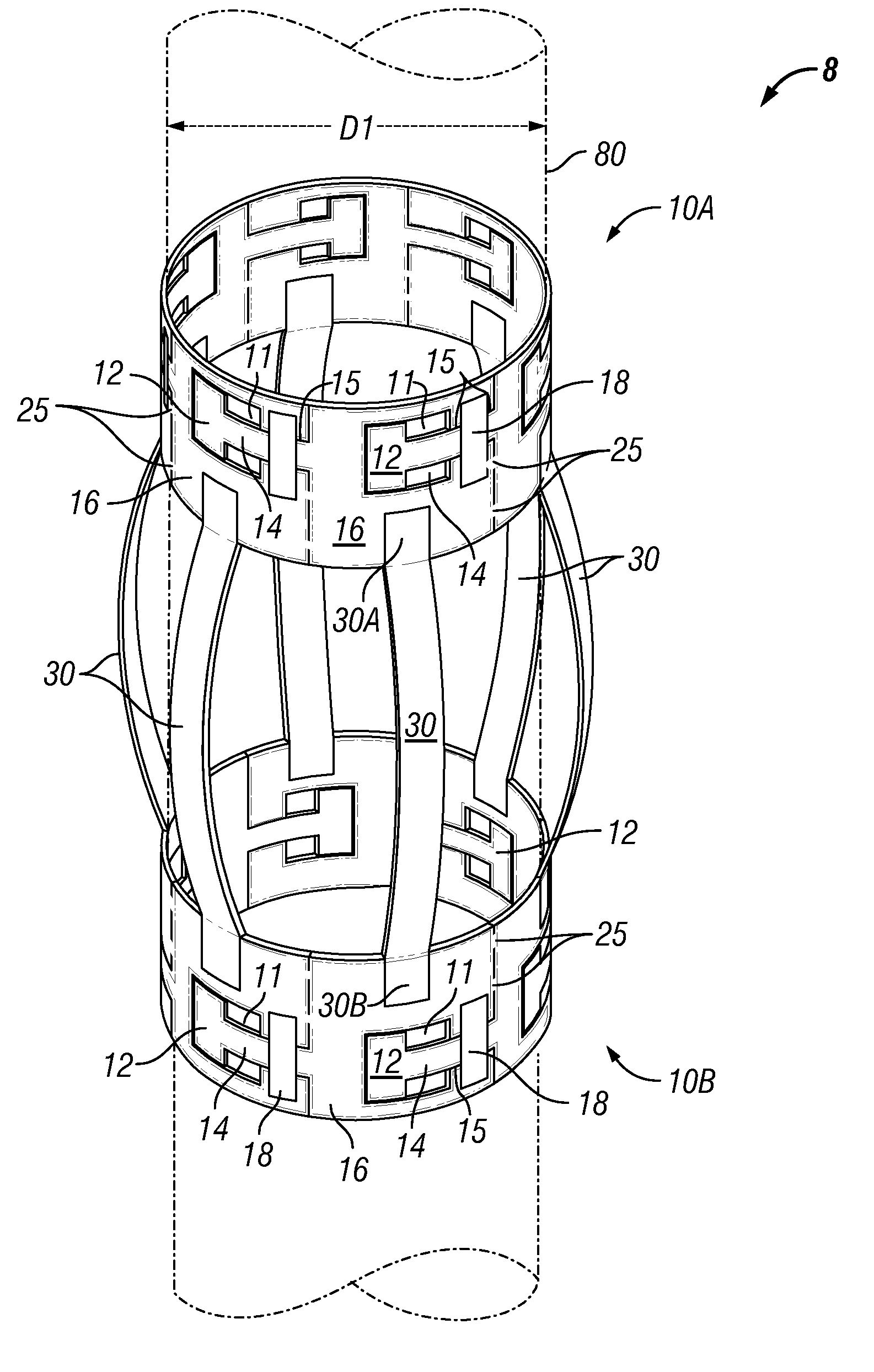
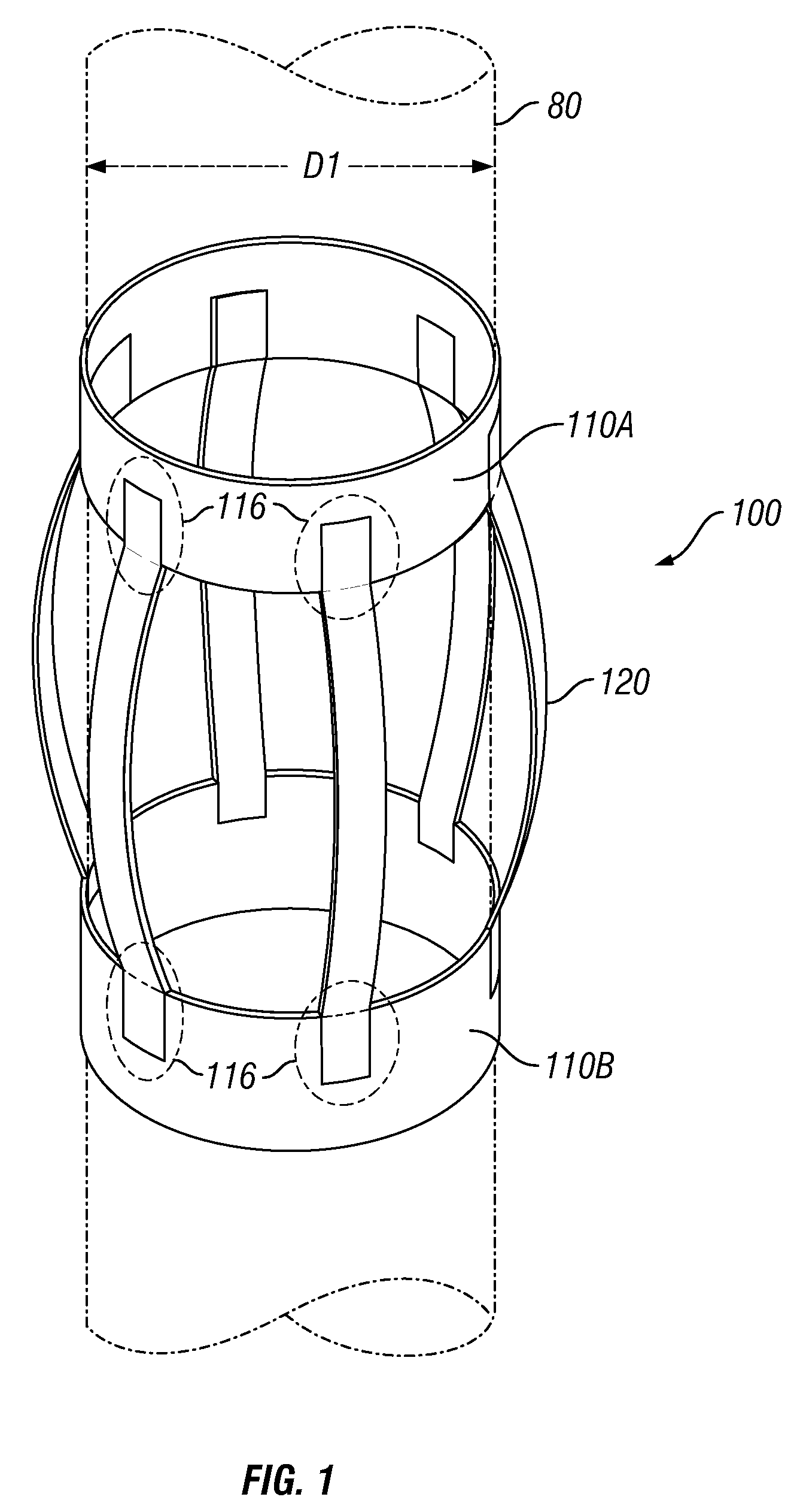
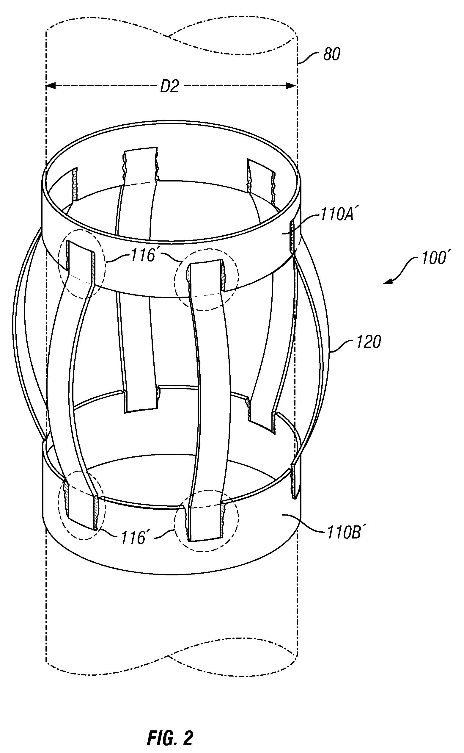
[0038]FIG. 3 illustrates one embodiment of an expandable centralizer 8 comprising a pair of opposed, expandable end collars 10A, 10B (hereinafter “expandable collars”) and a plurality of generally angularly distributed bow springs 30. The expandable collars 10A, 10B each have a bore, and the bores of the two expandable collars are generally aligned, one with the other, to receive a generally linear and expandable pipe segment 80 there through.

[0039]The illustrated bow springs 30 each have a first end 30A connected to the first expandable collar 10A, and a second end 30B connected to the second expandable collar 10B. Each bow spring 30 is shown in FIG. 3 in its deployed and outwardly bowed configuration, and each is generally flexible and collapsible to lie generally along a portion of the exterior surface of the pipe segment 80 that may be received through the aligned bores of the expandable collars 10A, 10B. When collapsed, e.g., to lie along the exterior of the pipe segment 80, ea...


PUM

PropertyMeasurementUnit
thicknessaaaaaaaaaa
thicknessaaaaaaaaaa
diameteraaaaaaaaaa

Abstract

A close-tolerance expandable bow spring centralizer 8 having a first expandable collar 10A coupled to and spaced apart from a second expandable collar 10B through a plurality of bow springs 30 wherein expandable collars 10A, 10B comprise a plurality of slidably coupled links 16 that separate to expand the diameter of the collars 10A, 10B, e.g., upon expansion of an expandable pipe string 80 on which the centralizer 8 is received. Expandable bow spring centralizer 8 may grip the expandable pipe string 80 when in the collapsed configuration to eliminate the need for a stop collar. Additionally or alternatively, a fin 32 may be connected to each bow spring 30, and then connected to one or more adjacent fins 32 upon collapse of the bow springs 30 to form a restraining band 39 that may be ruptured, e.g., upon expansion of the expandable pipe string 80.

Description

STATEMENT OF RELATED APPLICATIONS[0001]The present application is a continuation-in-part application depending from U.S. application Ser. No. 11 / 749,544 filed on May 16, 2007 by applicants Jean Buytaert, et al. for a Low-Clearance Centralizer and Method of Making Centralizer. The present application is also a continuation-in-part application depending from U.S. application Ser. No. 11 / 828,943 filed on Jul. 26, 2007 by applicants Jean Buytaert, et al. for an Apparatus and Method for Deploying a Centralizer Installed on an Expandable Casing String. Both of these applications are assigned to the assignee of the present invention.BACKGROUND OF THE INVENTION[0002]1. Field of the Invention[0003]In one embodiment, the invention relates to a close-tolerance expandable centralizer to dispose an expandable pipe string to a desired position within a borehole. One embodiment of the invention is directed to an apparatus and a method to deploy an expandable centralizer, after it is received on an...

Claims


Application Information

Patent Timeline
Patent Type & Authority Patents(United States)
IPC IPC(8): E21B17/10
CPCE21B17/1028Y10T29/496
Inventor BUYTAERT, JEANMILLER, EUGENE EDWARDMCDOWELL, DONALD ELWIN
Owner INNOVEX DOWNHOLE SOLUTIONS INC
Why Eureka
Try Eureka