
Locking device for fixing a lid

a technology for locking devices and lids, which is applied in the direction of clamping mechanisms, closures, pressure vessels, etc., can solve the problems of high force effective on such lids, requiring precise and fail-safe locking devices, and comparatively large device parts, so as to reduce the risk of slipping, and facilitate the insertion on the other side.

Active Publication Date: 2011-02-01
NATEX PROZESSTECH
View PDF12 Cites 3 Cited by
  • Summary
  • Abstract
  • Description
  • Claims
  • Application Information

AI Technical Summary

Benefits of technology

[0008]Generally the inventive swivel arm for the linkage or flexible joint of the segments with the lid now allows a number of further enhancements relating to the reduction of the necessary displacement force. Particularly such a swivel arm enables the support of the segments in the lid in a floating or hanging position, in which frictional forces are eliminated. To this point a preferred embodiment is so designed, that the pivotable support of the segments on the lid comprises at least one pivotable shaft or pivot axle extending at right angles to the displacement movement of the segments, whereby a sliding or rubbing contact of the locking elements at the lid surface can be reduced or prevented if the segments are connected to the lid to be adjustable in an in axial direction of the pivot axis in the height direction.
[0011]Overall by the bilateral, autonomous actuation of each segment an insertion of the segments even in the case of unilateral frictional resistances is safeguarded, as no momentary stresses on the guides are in effect. The segments can each adapt in the desired way to the outline without guiding or adjustment measures, whereby the pivotable joint relative to the lid, i.e. a central linkage instead of a linearly guided one, entails that the construction becomes insensitive to deformation due to inner pressure and the segments can be inserted on the smoother-running side first, depending on the remaining frictional forces, whereby the insertion on the other side will be eased. The central linkage of the corresponding locking segments leads to a very unproblematic, tangential adjustment of the segment positions, which is of paramount importance for the final locking by insertion of the locking bolts. The overhung guidance of the segments allows for high and narrow segments to be used, which usually had a high tilting danger, as a corresponding support via the swivel axis and the bushing parallel to this axis occurs. The range of application of the locking device will be considerably extended in this way not only to higher pressures but also to larger locking diameters, whereby abrasion along a sliding surface can be eliminated and whereby also elaborate lubrication of sliding surfaces becomes dispensable. Particularly in the food sector such sliding surfaces to be lubricated would pose a hygiene problem. The segment actuators may not only be devised weaker but also in problematic circumstances may be moved by hand, as the frictional forces are generally eliminated. The linkage itself can be designed for a defined torsional behaviour, whereby the linkage not only carries the assigned segment but also allows for the segments to go along the elastic deformation of the locking system due to internal pressure onto the lid, without destroying the bearing of the linkage.
[0012]The use of said spring element allows for the exact setting up of the desired clearance and in this way for the guiding of the segment marginally above the lid, whereby the spring element facilitates particularly in the bracing into the locked position an according correction of the position in height, without overstraining the bearing.
[0013]The biaxial adjustability of the swivel axis leads to a tilting about two horizontal axes being at right angles to each other and thus to an accurate parallel adjustment of the segment to the lower support surface. All slated positions occurring due to deformation, bearing clearances and manufacturing imprecisions can thus be compensated for.
[0014]As already mentioned, this exact achievement of the locking position causes that the locking segments can be inserted easily. The embodiment is preferably designed so that the segments comprise at least two recesses or bearing eyes for the reception of locking members or locking pins.

Problems solved by technology

Particularly at wide diameters of lids and accordingly high pressures the force effective on such lids gets exceedingly high and requires precise and fail-safe locking devices.
For big containers this results in exceedingly heavy and comparatively big device parts.

Method used


Image

  • Locking device for fixing a lid
  • Locking device for fixing a lid
  • Locking device for fixing a lid

Examples


Embodiment Construction

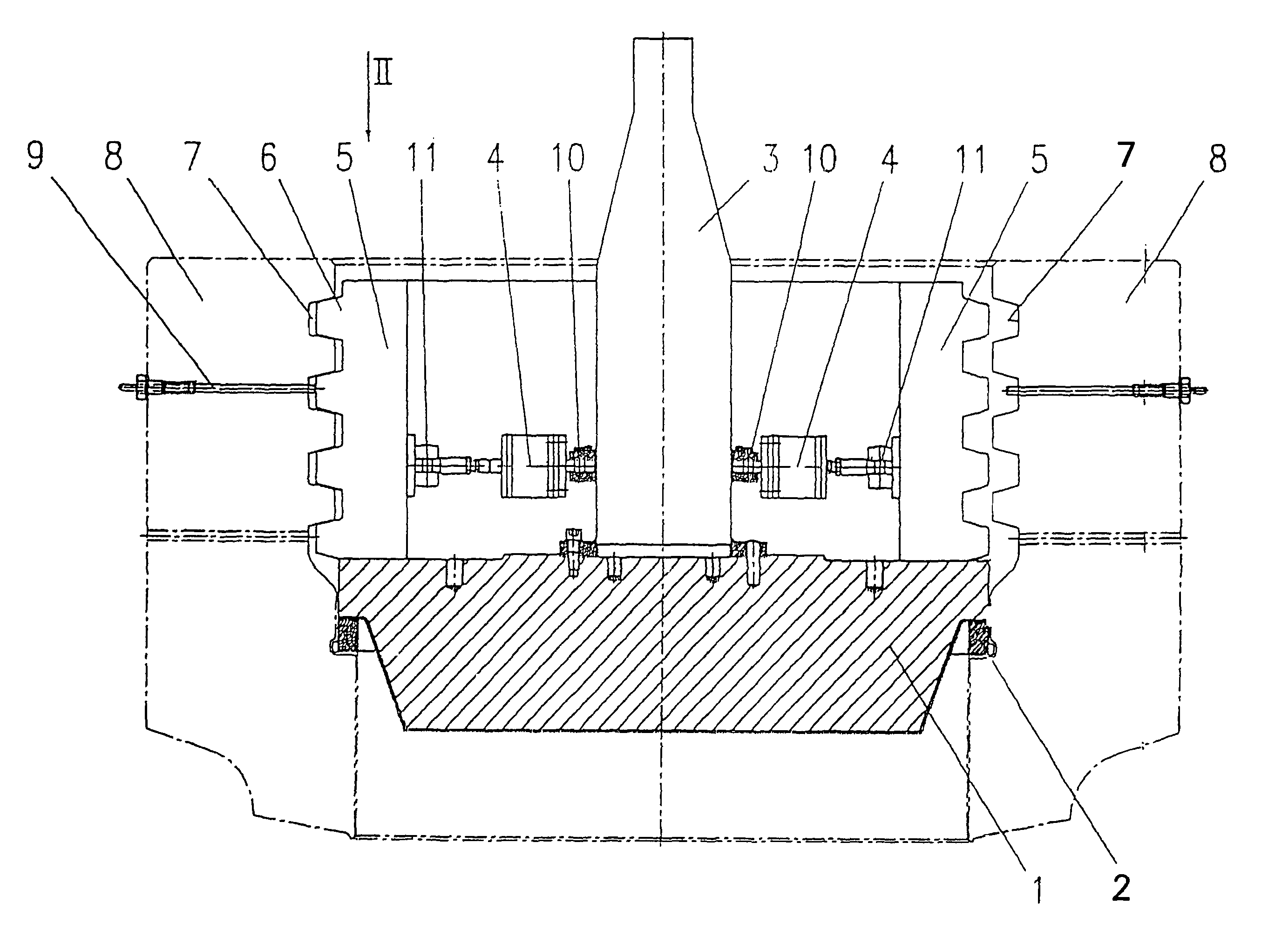
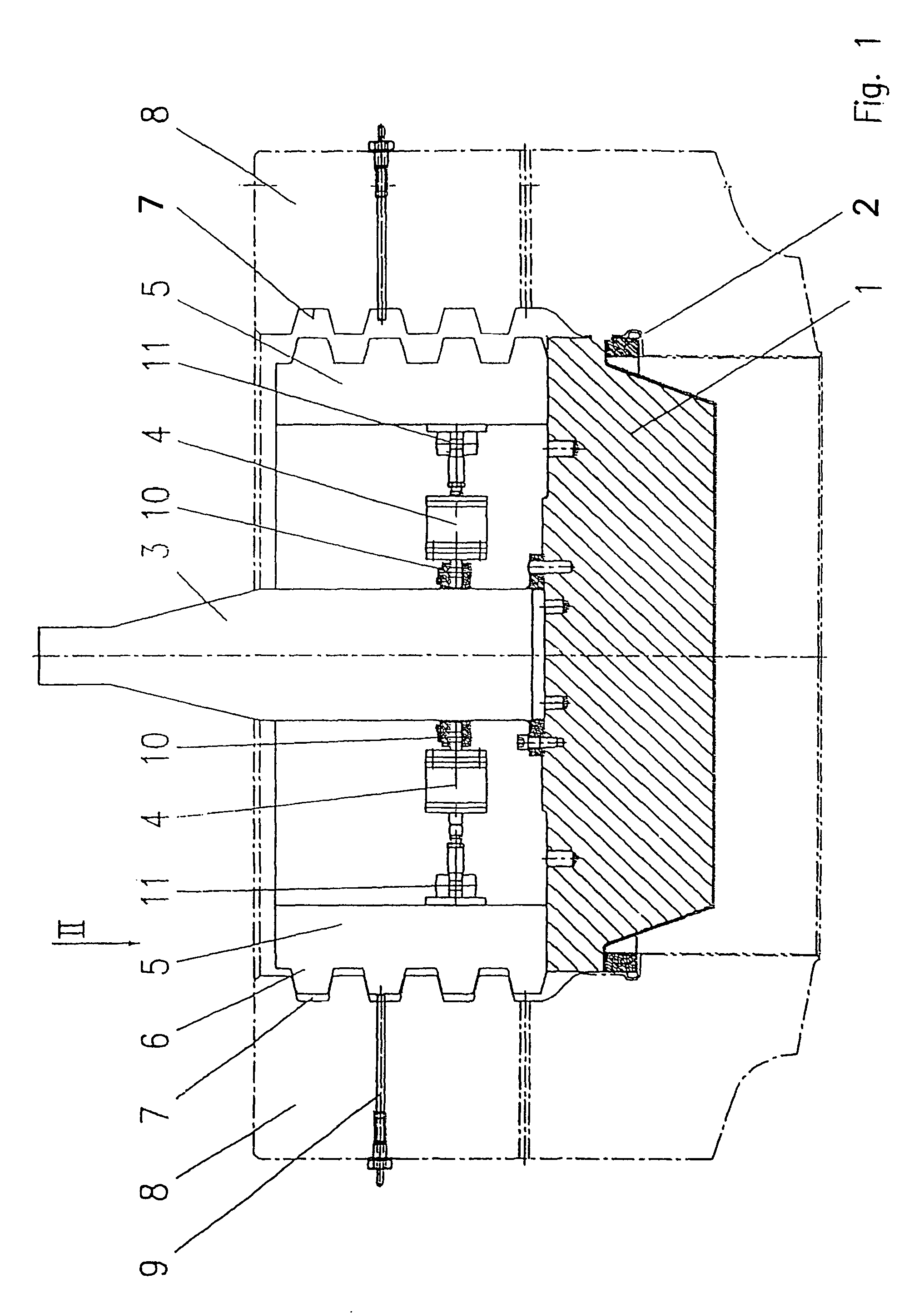
[0025]FIG. 1 shows a lid 1, which seats solidly on top of annular sealing elements 2. The lid 1 is raised or lowered by a central actuating rod 3, whereby this central actuating rod 3 simultaneously forms the counter bearing for hydraulic cylinder piston aggregates 4 for the actuator of the locking segments 5. The locking segments 5 on the left hand side of the drawing according to FIG. 1 are in the locking position and engage with their circumference ribs 6 with corresponding grooves 7 on the brink 8 of the container, whereby an actuating rod 9 for a position switch is schematically indicated. On the right hand side of the drawing according to FIG. 1 the segments 5 are still not engaged with the circumference grooves 7 on the brink 8 of the container.

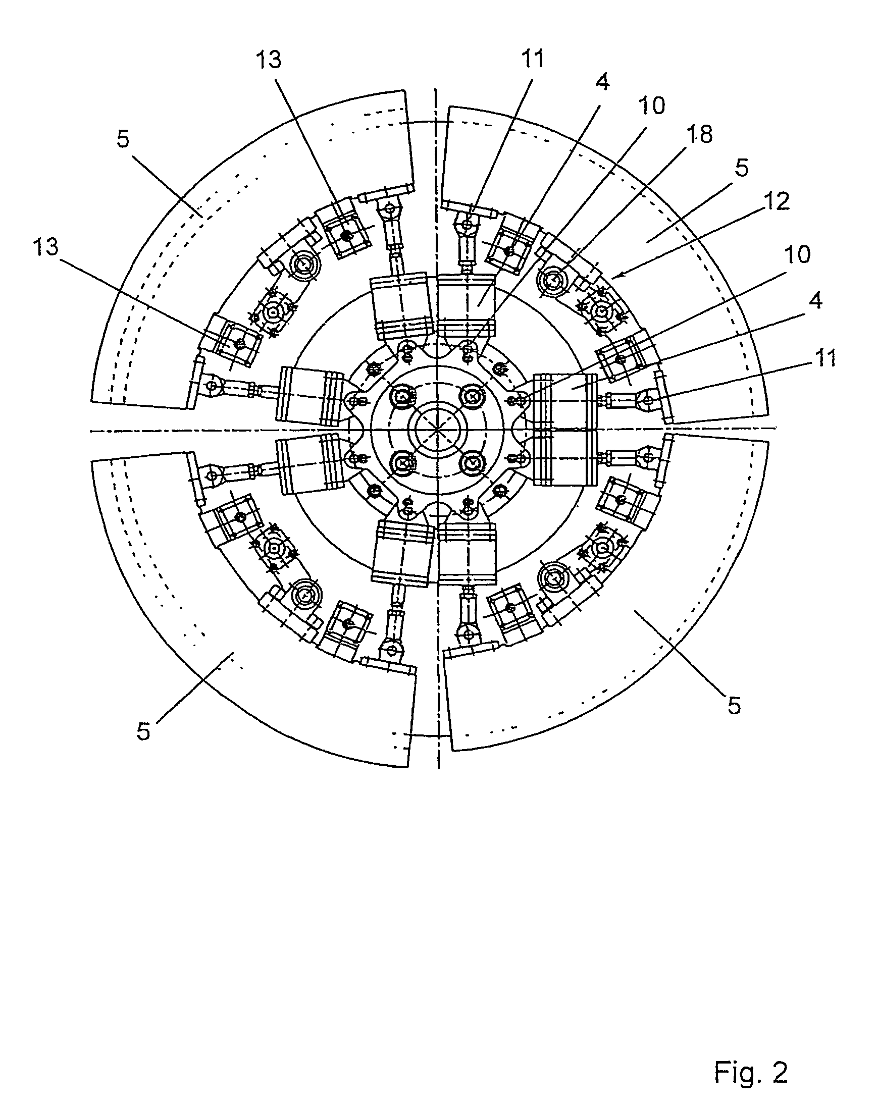
[0026]The cylinder-piston aggregates 4 are via hinge bearings 10 flexibly connected with the device part connected with the lid 1, namely, the actuating rod 3. Further the cylinder-piston aggregates 4 engage via pivot bearings 11 with ...


PUM


Abstract

In a locking device for the fixation of a lid (1) on an opening (8) of a pressure container with at least two locking segments (5) displaceable at right angles to the axis of the opening 98), which segments (5) bear protrusions (6) and groove-like recesses along their circumference, which in the locked position cooperate with recesses (7) and protrusions along the brim of the opening (8), the displacement actuator (4) of the segments (5) is linked to the segments (5) and to at least one point of application that is on the lid (1) or on a member (3) connected to the lid (1). The segments (5) are arranged in the direction of the circumference of the lid (1) and are pivotably supported on the lid (1) by a swivel arm (16), separate from the displacement actuator (4), being interposed.

Description

[0001]This application is a national stage completion of PCT / AT2005 / 000043 filed Feb. 10, 2005 which claims priority from Austrian Application Ser. No. A 195 / 2004 filed Feb. 10, 2004.FIELD OF THE INVENTION[0002]The invention relates to a locking device for the fixation of a lid on an opening of a pressure container with at least two locking segments displaceable at right angles to the axis of the opening, which segments bear protrusions and groove-like recesses along their circumference, which in the locked position cooperate with recesses and protrusions along the brim of the opening, whereby the displacement actuator of the segments is linked to the segments and to at least one point of application that is on the lid or on a member connected to the lid.BACKGROUND OF THE INVENTION[0003]Pressure containers, and specifically tubular pressure containers, are used inter alia in chemical engineering. Particularly at wide diameters of lids and accordingly high pressures the force effecti...

Claims


Application Information

Patent Timeline
Patent Type & Authority Patents(United States)
IPC IPC(8): B65D45/00B65D45/28B65D45/32B65D45/34F16J13/08F16J13/10
CPCF16J13/08F16J13/10F16J13/00
Inventor MEINDL, PETERLANG, FRANZLACK, EDUARDGLANZ, ERNSTSEIDLITZ, HELMUTTRUKSES, ALBERT
Owner NATEX PROZESSTECH
Learn More