Method for anion-exchange adsorption and thioether anion-exchangers

a technology of anion exchange and anion exchanger, which is applied in the direction of ion exchange, peptides, combustible gas purification/modification, etc., can solve the problem that none of the methodologies in these three articles describe the successful desorption process under

Active Publication Date: 2011-02-01
CYTIVA BIOPROCESS R&D AB
View PDF5 Cites 0 Cited by
  • Summary
  • Abstract
  • Description
  • Claims
  • Application Information

AI Technical Summary

Benefits of technology

[0028]b) to provide anion-exchange media that can have a reduced ligand content while retaining a sufficient capacity to bind target substances;
[0031]e) to design anion-exchangers that can resist regeneration and / or cleaning with alkaline and or acidic milieu without significant loss of chromatographic properties;
[0035]i) to provide simplified processes involving anion-exchangers, for instance to improve productivity and / or reduce the costs for process equipment and investments;
[0037]k) to provide opportunities for novel combinations of separation principles based elution of anion exchange adsorbents at high salt concentration, for instance hydrophobic interaction adsorption after an ion exchange step.
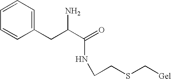
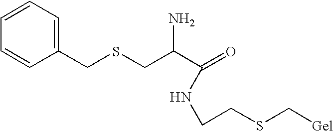
[0039]The present inventors have discovered that ligands containing a thioether linkage in the proximity of the positively charged nitrogen atom may provide anion-exchangers that at least partially meet these objectives. The present inventors have also discovered that inclusion of additional atoms or groups participating in electron donor-acceptor interactions in the proximity of the positively charged atom in the anion-exchange ligands may enhance the strength of the interaction between the substance and the adsorbent.

Problems solved by technology

None of the methodologies in these three articles describe successful desorption processes under anion-exchange conditions.

Method used


Image

  • Method for anion-exchange adsorption and thioether anion-exchangers
  • Method for anion-exchange adsorption and thioether anion-exchangers
  • Method for anion-exchange adsorption and thioether anion-exchangers

Examples


Embodiment Construction

Part I

Synthesis of Anion-Exchangers

General:

[0153]Volumes of matrix refer to sedimented bed volume. Weights of matrix given in gram refer to the suction dried weight. It is understood that these matrices are still water solvated material. For reactions on a large scale, stirring refers to the use of a suspended, motor-driven stirrer since the use of a magnet bar stirrer will to damage the beads. Small-scale reactions (up to 20 ml) were performed in closed vials on a shaking-table. Determination of the functionality and the extent of allylation, epoxidation, or the degree of substitution of ion exchanger groups on the beads were made using conventional methods. Elementary analyses of the gels were also performed especially for analysing of the sulphur content.

[0154]A typical example for preparing the anion-exchangers described above is exemplified below using Sepharose 6 Fast Flow (Amersham Pharmacia Biotech, Uppsala, Sweden) as the base matrix.

1. Introduction of Allyl Groups on the M...


PUM

PropertyMeasurementUnit
diametersaaaaaaaaaa
conductivity/ionic strengthaaaaaaaaaa

Abstract

A method for the removal of a substance, which has a negative charge and which is present in an aqueous liquid (I). The method comprises the steps of: (i) contacting the liquid with an anion-exchanger (1) that comprises mixed mode anion-exchanging ligands in which there is a positively charged nitrogen allowing binding of the substance to the anion-exchanger; and (ii) desorbing said substance from said anion-exchanger. The characteristic feature is that (A) the mixed mode ligands have a thioether linkage within a distance of 1-7 atoms from their positively charged atom, and (B) the anion-exchanger (1) (i) is capable of binding the substance of interest in an aqueous reference liquid (II) at an ionic strength corresponding to 0.25 M NaCl, and (ii) permits in the pH interval 2-12 a maximal breakthrough capacity for the substance which is ≧200% of the breakthrough capacity of the substance for Q-Sepharose Fast Flow (anion-exchanger 2).

Description

FIELD OF INVENTION[0001]The present invention relates a method for the removal of a compound (=substance) carrying a negative charge from an aqueous liquid (I). The method comprises the steps of:[0002](i) contacting the liquid with an anion-exchanger that comprises a base matrix carrying a plurality of mixed mode anion-exchanging ligands (anion-exchanger) in which there is a positively charged nitrogen under conditions permitting binding between the ligands and the substance, and[0003](ii) desorbing said substance from said anion-exchanger by the use of a liquid (liquid (II)).[0004]The invention also relates to novel anion-exchangers in which there are mixed mode anion-exchange ligands.[0005]The terms “carrying a negative charge” and “negatively charged” mean that the substance carries one or more negative charges and / or has a negative net charge.[0006]The terms “mixed mode anion exchange ligand” and “bimodal anion exchange ligand”, in the context of this invention, refer to a ligan...

Claims


Application Information

Patent Timeline
Patent Type & Authority Patents(United States)
IPC IPC(8): B01D15/00B01D15/32B01J20/281B01J20/34B01J41/04B01J41/08B01J41/12B01J41/20B01J49/00C02F1/28C02F1/42C07K1/18
CPCB01D15/327B01J41/085B01J41/20C02F1/42B01J41/09
Inventor BELEW, MAKONNENJOHANSSON, BO-LENNARTMALOISEL, JEAN-LUC
Owner CYTIVA BIOPROCESS R&D AB
Why Eureka
Try Eureka