Method for operation of a two-stranded electronically commutated motor, and motor for carrying out said method

a technology of electronically commutated motors and motors, which is applied in the direction of multiple motor speed/torque control, synchronous motor starters, automatic controllers, etc., can solve the problems of fan almost or entirely inaudible, fan service life is longer, and the effect of reducing the risk of loss of temperature information

Active Publication Date: 2011-02-01
EBM PAPST ST GEORGEN & -
View PDF12 Cites 33 Cited by
  • Summary
  • Abstract
  • Description
  • Claims
  • Application Information

AI Technical Summary

Problems solved by technology

The result of this is that such fans have a longer service life, and at low temperatures a fan of this kind is almost or entirely inaudible, since it is running slowly.
With fans of this kind, which must be very inexpensive, the problem arises of mapping the temperature information contained in a PWM signal of the kind described onto the rotation speed of the motor or fan as completely as possible and in the manner of a conformal mapping; in other words, as little as possible of this temperature information should be lost.
This is undesirable, because conformal mapping is not taking place, and because the risk exists that the object to be cooled will overheat.

Method used


Image

  • Method for operation of a two-stranded electronically commutated motor, and motor for carrying out said method
  • Method for operation of a two-stranded electronically commutated motor, and motor for carrying out said method
  • Method for operation of a two-stranded electronically commutated motor, and motor for carrying out said method

Examples


Embodiment Construction

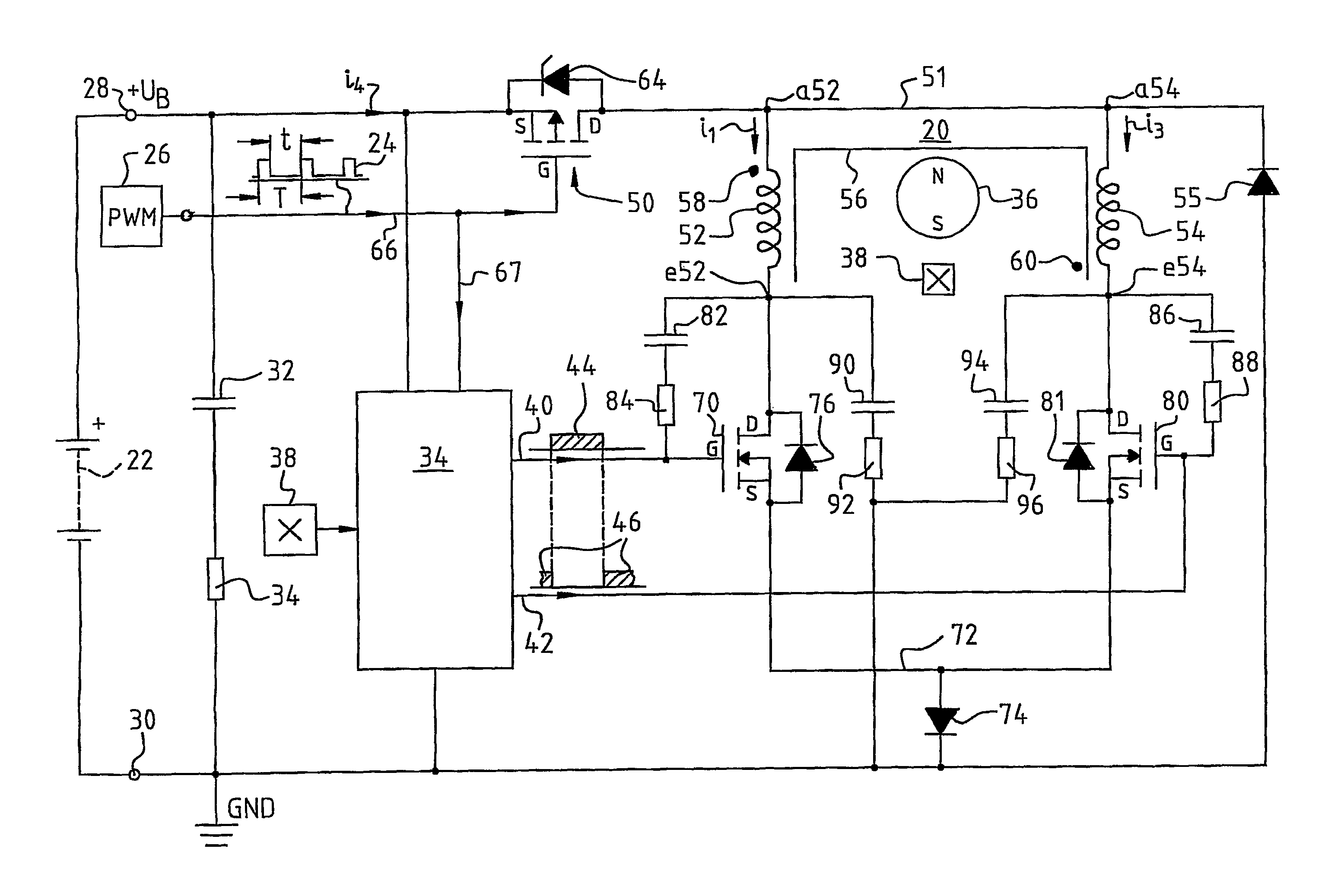
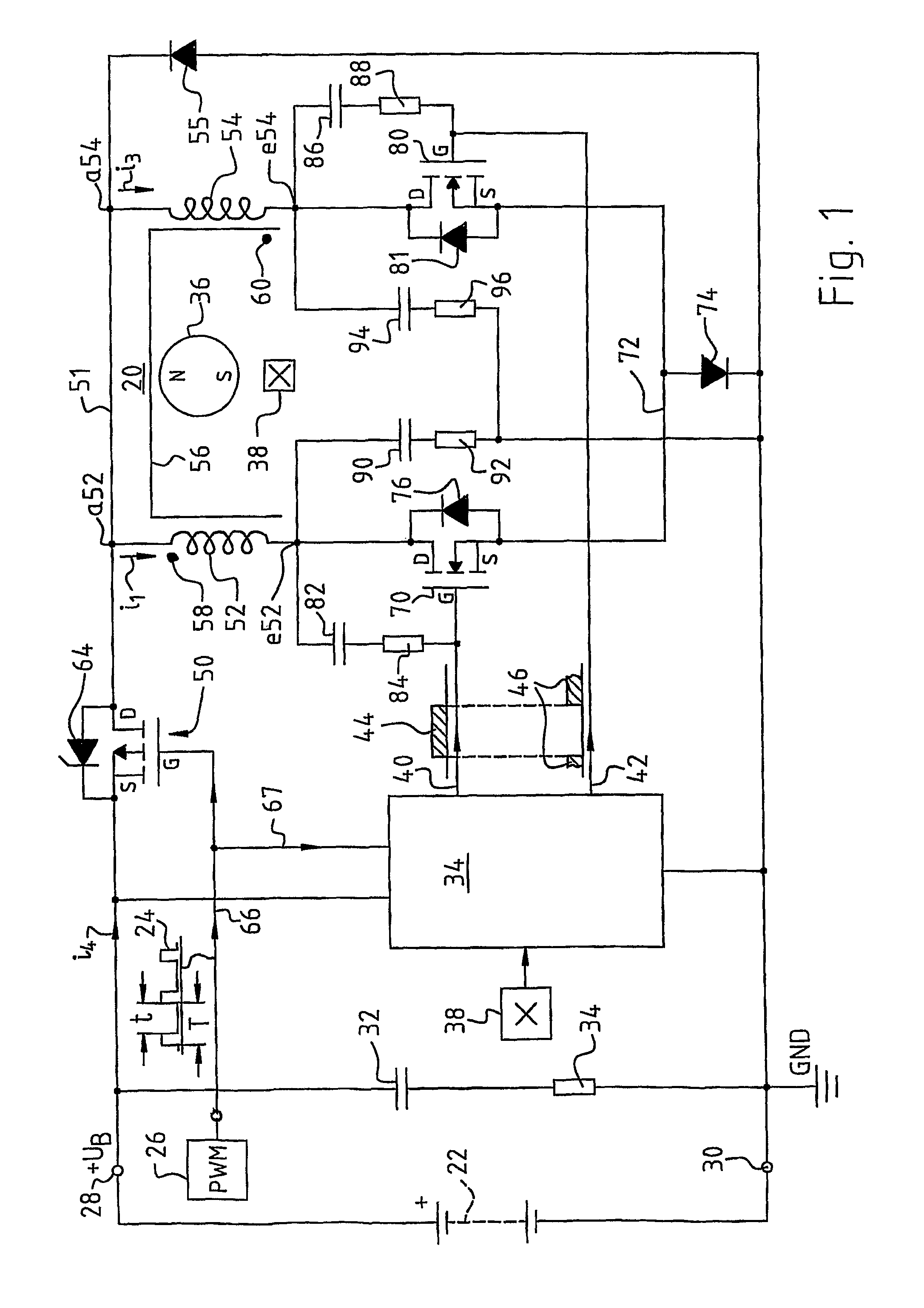
[0018]FIG. 1 shows a preferred embodiment of an electronically commutated motor 20 according to the invention. The motor obtains its energy from any DC source 22, which is depicted symbolically as a battery but is usually configured as a power supply powered from an alternating-current or three-phase power grid, as is known to one skilled in the art. The left half shows a “DC link” circuit.

[0019]The rotation speed of motor 20 is controlled by means of a PWM signal 24 that is generated by any PWM generator 26 and that has, for example, a frequency in the range from 16 to 30 kHz, preferably approximately 25 kHz. The period length of signal 24 is labeled T in FIG. 1, and its pulse duration is labeled t. The ratio

pwm=t / T*100%  (1)

is referred to as the “duty factor” (or “PWM duty cycle”). In other words, when t=T, the duty factor pwm=100%.

[0020]Any item of information can be encoded into this duty factor, e.g. a datum regarding temperature, relative humidity, radioactivity, etc. It is us...


PUM


Abstract

A two-stranded electronically commutated DC motor has a permanent-magnet rotor (36), power supply terminals (28, 30) for connecting the motor to a current source (22) and a stator (102) having a winding arrangement which includes first and second winding strands (52, 54). The latter are controlled by respective first and second semiconductor switches (70, 80). The motor also has a third controllable semiconductor switch (50), arranged in a supply lead from one of the terminals (28, 30) to the winding strands (52, 54), which third switch is alternately switched on and off by applying to it a PWM (Pulse Width Modulated) signal 24. During switch-off intervals, magnetic flux energy stored in the motor causes a decaying loop current (i2) to run through the windings, continuing to drive the rotor. This facilitates conformal mapping of temperature information in the PWM signal onto a target motor rotation speed.

Description

CROSS-REFERENCE[0001]This application is a section 371 of PCT / EP2006 / 00483, filed 20 Jan. 2006, and published 21 Aug. 2006 as WO 2006-089605-A. It further claims priority from German application DE 20 2005 003 414.2, filed 24 Feb. 2005, which is incorporated by reference.FIELD OF THE INVENTION[0002]The present invention relates to a method of operating a two-stranded electronically commutated motor, and to a motor adapted for carrying out such a method. The invention refers preferably to motors of low and moderate output such as those used to drive fans that could be characterized, for example, using the term “compact fans” or “equipment fans,” e.g. in an output range from approximately 0.5 W to approximately 30 W, preferably approximately 3 W to approximately 20 W.BACKGROUND[0003]In the context of such fans, a desire exists for them to run at full output, i.e. at a rotation speed of, for example, 4000 rpm, only when the temperature of the object to be cooled is high. It is possible...

Claims


Application Information

Patent Timeline
Patent Type & Authority Patents(United States)
IPC IPC(8): H02P7/29
CPCH02P6/24H02P6/22
Inventor FOLL, CLAUSJESKE, FRANKKUNER, ARNOLDLOFFLER, JENS
Owner EBM PAPST ST GEORGEN & -
Why Eureka
Try Eureka